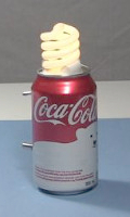
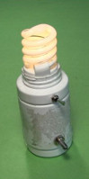
Joule thief circuit powering a compact fluorescent lightbulb
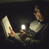
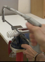
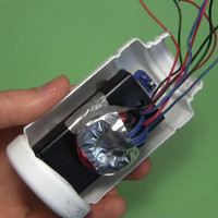
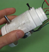
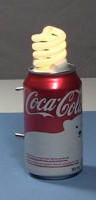
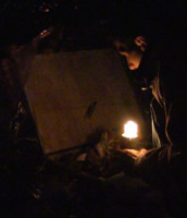
Following the tips outlined below, you can use the joule thief circuit to power a compact fluorescent lightbulb (CFL) using just some AA batteries. The approach below is popularly known as Jeanna's light ( here's Jeanna's youtube channel.) In the photos below you can see I've put it in a soda can and I'm using it to read by!
See the videos below to watch it in action along all sorts of testing and even step-by-step instructions for making it.
How to make the joule thief circuit for power a CFL
Below is the circuit diagram for what worked for me. The trickiest part was getting the right windings on the ferrite toroidal core. It's only around a 1 1/4" (3.5 cm) outer diameter and 5/8" (1.875 cm) outer diameter toroid so it had to be very efficient while not having the insulation on the coils breakdown from the high voltage.
Note that toroid was pretty randomly selected, meaning you can use a larger one and put on more turns. Using a smaller one though, would mean less turns and a lower output voltage to the CFL that may not work, or would require a fairly low wattage CFL with a short tube length. There's usually one of these toroids in microwave ovens.
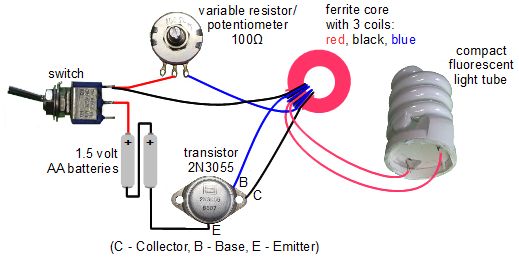
The normal joule thief circuit has only two coils, but as you can see in the above circuit diagram, this one has three. That third coil and the CFL are the only additions to the regular joule thief circuit. There's also one change and that's to change the normal low power transistor for a power transistor.
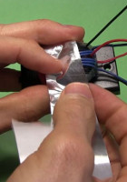
Cutting open (or gutting) the Compact Fluorescent Light (CFL)
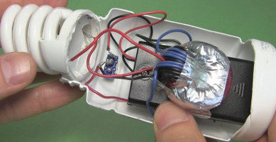
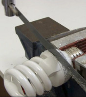
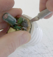
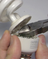
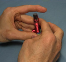
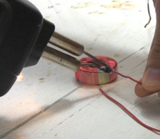
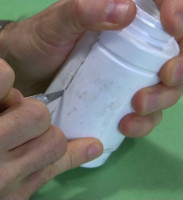
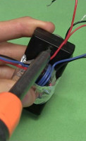
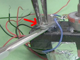
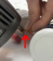
The only part of the CFL you need is the spiral fluorescent tube and the wires that are connected to it. Inside the base of the CFL are a whole bunch of electronics parts which you can discard or reuse for something else. Sometimes you can just pry it open using a sharp edge, like a knife, but usually I have to cut it open. I use hack saw for this, but most any saw will do (see photos below.) Make many shallow cuts all around the circumference. Don't cut too deeply otherwise you may cut the wires inside shorter than you'd like to. Just cut the case.
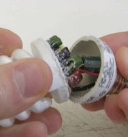
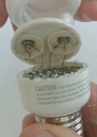
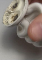
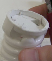
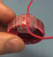
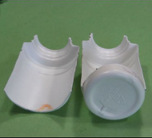
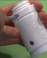
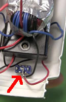
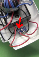
Once you've cut the case in two, pry it open as much as you can. Depending on where you made your cut, you'll either see electronic parts like the third photo above, or the back of a circuit board like in the fourth photo.
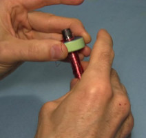
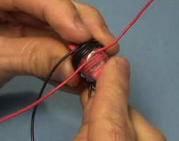
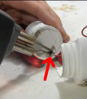
You want to get at the area just behind the tube. There are two pairs of wires there and you want to cut those wires as near to the circuit board as possible, leaving as long a length as possible still connected to the tube. In the first photo below I'm using a knife to slice the wires and in the second photo it's much easier to get at them and just cut them with scissors or wire cutters.
And the last two photos on the right above are examples of the end results, what are often referred to as gutted CFLs.
Winding the coils
The coils are wound on a toroid core. You'd think a ferrite core would be best but an iron powder core works quite well, as in my case. Most of the cores you scavenge from old equipment are iron powder cores.
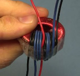
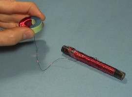
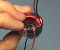
The first coil is the one with many, many turns. It's the red one in the above diagram. I fit around 256 turns. Keep each winding next to each other with as little gap as possible and as few overlaps as possible. Use a small diameter, enamel coated wire so you can fit as many turns as possible. I used 30 gauge (AWG) magnet wire. To make it easy to wind, first wrap the wire around a stick of some sort, as shown in the photos below.
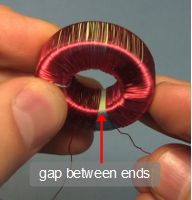
Stop winding when you have about 1/8" or a few millimeters gap between the first and current winding on the inside of the toroid (see photos below.) This is because there will be a high voltage between these two ends and the enamel insulation isn't enough to prevent voltage breakdown between them.
Instead, solder on some wire with thicker insulation. I used red 18 AWG plastic coated wire. The wire size doesn't matter; it's the use of a plastic coated wire that's important in order to get the thick insulation. Do this for both ends and continue winding both ends until they meet. Wrap the end with tape to help with insulation and provide a flat winding surface for the next coil (see photo below.)
Then, as shown in the first two photos below, wind 10 turns of a plastic insulated wire on top of the first coil. I used black 18 gauge (AWG) plastic coated wire. Again, the wire size doesn't matter; it's the use of a plastic coated wire that's important in order to get the thick insulation. Start winding on one side of where the first coil ended and end on the other side. Wind in the same or opposite direction as the first coil. It works either way.
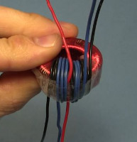
Lastly, as shown in last photo above, wind 5 turns of a plastic insulated wire on top of the second coil. I used blue 18 gauge (AWG) plastic coated wire. Once again, the wire size doesn't matter; it's the use of a plastic coated wire that's important in order to get the thick insulation. Start winding on one side of where the first coil ended and end on the other side. Wind in the same direction as the second coil.
Wrap everything well with tape so nothing comes loose.
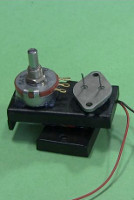
Assembling all the other parts
The first few steps involve attaching components to things before wiring them up.
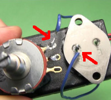
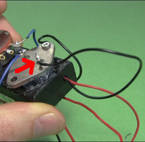
The following photos show connecting both ends of the blue coil and one end of the black coil. Be careful which ends go where. Doing this wrong is the most common mistake. Follow the diagram above closely.
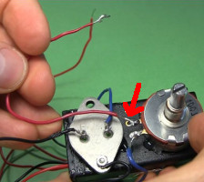
Next come the connections to the switch.
Next comes soldering the compact fluorescent light's (CFL's) wires to the red coil. There are two pairs of CFL wires. One pair goes to one end of the red coil and the other pair goes to the other end of the red coil. The polarities don't matter here; either end of the red coil goes to either pair. Note that on some CFLs I couldn't solder to the wires. Perhaps I wasn't using enough heat, though I was using a 150 watt soldering gun. Just be aware that you may have to connect some other way.
Some photos of the joule thief powered CFL in use
Video - How to Make Joule Thief Light a CFL - Jeanna's Light
This is a video I made showing step-by-step how to make this joule thief circuit, including the tricky coils, along with some demonstrations.
Video - Fun with Joule Thief Powering a CFL
In this is a video I do various measurements of the circuit: voltage, light brightness, ... plus how to use a PNP transistor with the joule thief circuit instead of the NPN transistor.
Other joule thief stuff

