Adding laser diodes to Star Wars TIE Fighter and Star Trek Enterprise models
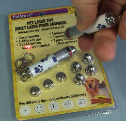
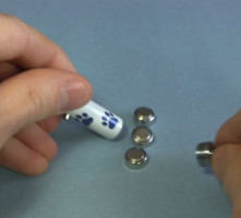
Laser diodes are easily and cheaply available from dollar stores and that includes batteries (see photo below.) They're intended as toy for pets. I wanted to fit these inside a Star Trek Enterprise model and a Star Wars TIE Fighter model. To do so I had to reduce the laser pointers to as little as possible.
WARNING Do not point the laser light directly into your or anyone's eyes. Also be careful of where the laser light may reflect from, such as reflecting off of a mirror and into someone's eyes.
Taking apart the laser pointer
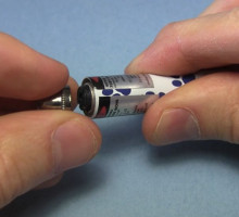
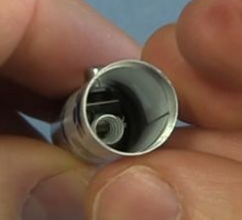
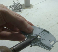
The first step is to unscrew the front cap since its only purpose is to contain lenses for projecting different shapes on a wall or floor. Then unscrew the back to remove the batteries and see inside for how much of the cylinder is safe to cut away.
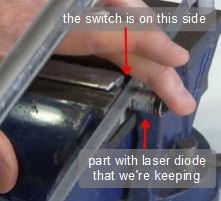
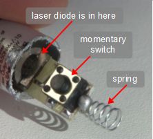
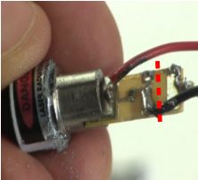
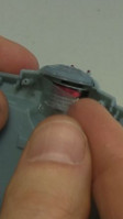
I then cut the cylinder as shown below, just a little further past the switch. Don't make deep cuts. Instead make a shallow cut, then rotate the cylinder and make another cut, and so on all around.
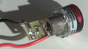
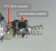
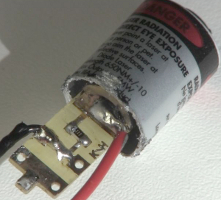
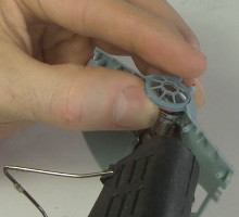
The result is in the middle and right photos. The laser diode itself is inside the thick cylindrical housing. One side of that is connected to 111 ohm resistor and from there on to the momentary switch. The other end of the switch is connected to a spring which goes to the negative of the batteries. The return path from the positive of the batteries was through the cylinder itself and back to the laser diode somewhere.
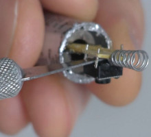
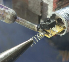
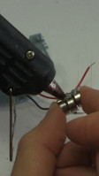
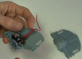
Next came removal of the switch and spring as shown below. I turned it over, bent the switch legs straight, and used a knife to tilt one side up. The legs on the other side were soldered in place. I then desoldered the spring and the remaining legs of the switch to remove them both. You can see the end result on the right below.
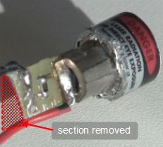
On the right you can also see that I soldered a black wire to where the switch was on the side that it connected to the resistor. I also carefully soldered a red wire to the metal plate just in front of the thick cylinder. This had to be done with very little heat since too much heat would damage the laser diode.
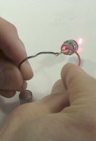
As you can see below, I then cut back more of the cylinder to the absolute minimum that I could (the photo is of a different version of the board but only cosmetically.) You can also see a dotted line where I needed to cut to get rid of the unneeded part of the circuit board. The minimum result is shown in the middle below. And on the right I'm testing it with a stack of the batteries. It still worked.
At this point you have a much smaller laser diode that can be inserted in all sorts of places.
WARNING Do not point the laser light directly into your or anyone's eyes. Also be careful of where the laser light may reflect from, such as reflecting off of a mirror and into someone's eyes.
Add the laser to a TIE Fighter and an Enterprise model
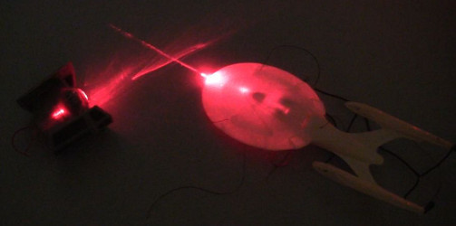
I had both these models, a TIE Fighter from Star Wars and an Enterprise from Star Trek. The original reason for reducing the size of the laser was to fit some into these models.
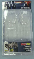
The TIE Fighter is the Snap Tite one by Revell (see the packaging below.)
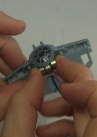
The first thing I had to do was use a hot iron to melt some of the plastic away on the bottom plate to make room for the circuit board. Once I'd done that I hot glued the laser to the place where Darth Vader normally sits.
Then I saw that I could fit the batteries in the same area just above the laser if I offset them a bit, as shown on the right below.
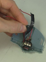
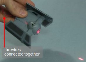
As shown below, I then hot glued the batteries together in the slightly offset shape. Before putting them in place I added a little tape over the laser to electrically insulate it from the batteries, since the laser's outer cylinder was a part of the original circuit. I then taped the black wire that I'd soldered to the laser's circuit board to the negative side of the battery stack, and taped an extra red wire to the positive side. As you can see in the rightmost photo, that leaves me with two red wires, the one I'd just taped to the positive of the battery and the one I'd soldered to the laser's circuit board. Touching the two ends of these together acts like a switch, turning on the laser, as shown in the photo below all the others.
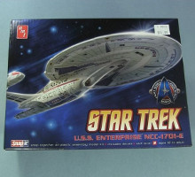
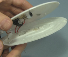
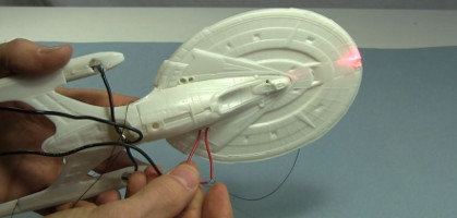
And below are the photos of putting one of these laser diodes in the Star Trek Enterprise model. The model is a snap it model by AMT and it's the Enterprise NCC-1701-E.
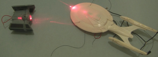
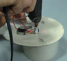
I hot glued the laser, the batteries and the wires to the underside of the top saucer plate. Notice in the rightmost photo below that I had to melt some holes in the bottom plate to make room. And in the photo below all the others you can see that when I connect the two wires, the laser turns on.
Video - Adding Lasers to Star Wars TIE Fighter and Star Trek Enterprise Models
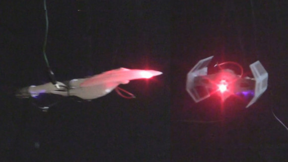
Here's my video showing step-by-step cutting the laser pointer down to just the laser diode and then putting it in the TIE Fighter and the Enterprise. At the end is a fun, cheesy short where they have a space battle against each other.
Video - How to add Ion Propulsion to Star Wars TIE Fighter Model
In this video I add ion propulsion to the TIE Fighter and show it flying on a rotor along with an ion propelled Enterprise, both with their lasers turned on. You can see the details for where I added ion propulsion to the Enterprise here.
