Pin headers - soldering, cutting, both male and female
Modern elecronics projects often involve using commercially made boards like Arduinos, Raspberry Pis and support boards like sound boards, motor controllers, and so on. All these expect to be connected to using male or female pin headers. This page talks about working with those pin headers.
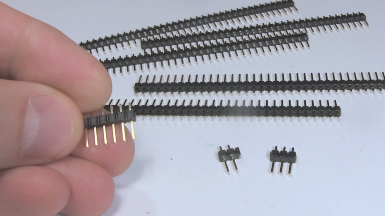
Male pin headers
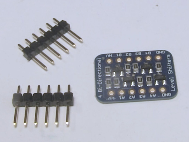
Male pin headers are most often encountered when you buy a board that you're expected to plug/insert into a circuit somewhere, often by inserting it into some female pin headers. To keep costs down, the manufacturer often sends you the board and pin headers but expects you to solder them to the board.
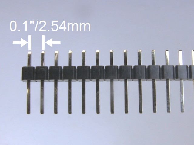
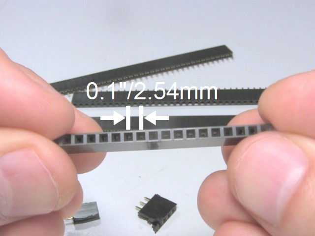
One thing to keep in mind is that you have the right pin headers for the job. The spacing between the pins is important. In the example shown here they are 0.1 inches/2.54mm apart.
You can buy pin headers from places like ebay.com, Adafruit.com, and sparkfun.com.
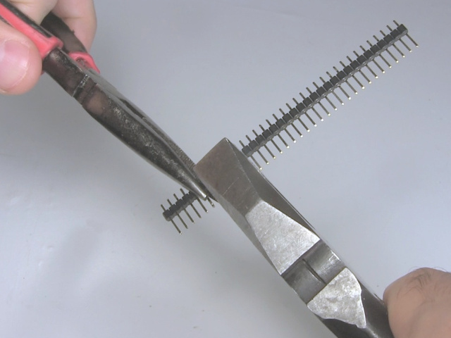
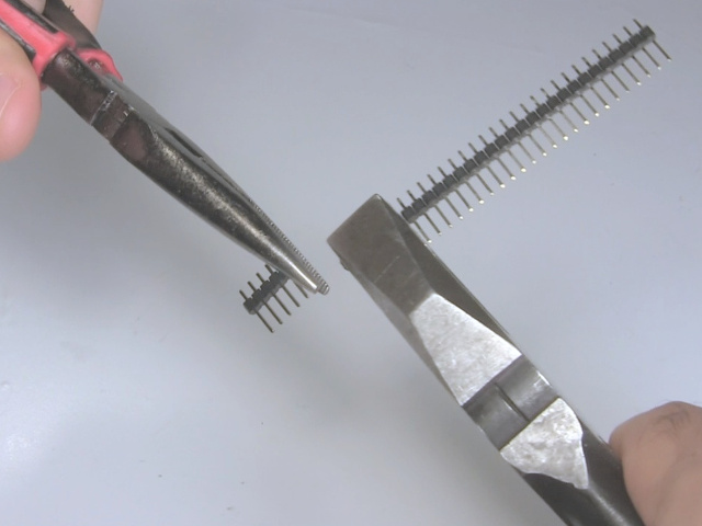
Breakaway headers
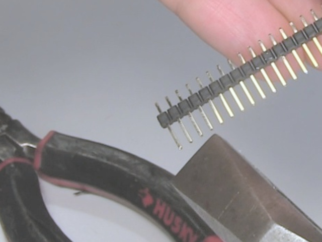
The male pin headers shown here are breakaway headers, meaning you can easily break them apart to get the number of pins you want. Simply count out the number of pins you want, grip the next pins firmly with something like pliers, and then use another set of pliers to break the desired pins off. They break fairly easily this way.
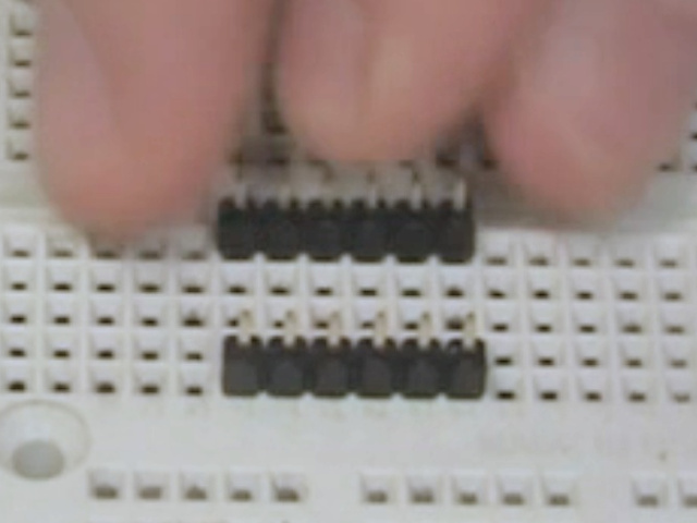
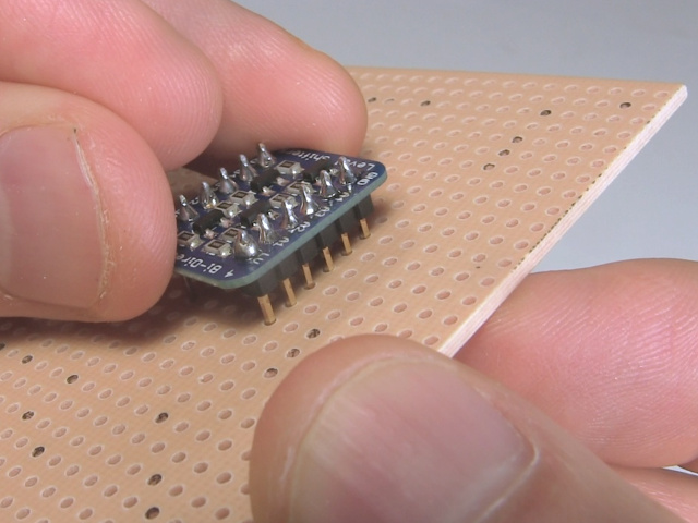
Solder male pin header
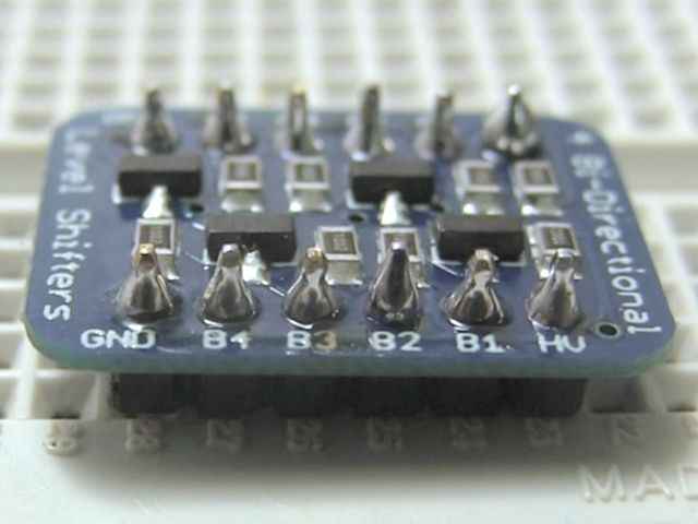
To solder male pin headers to a board, first put the pin headers in a breadboard. That's optional, but it's a great way to make sure the pin headers will be perpendicular to the board and parallel to each other, making it easy to insert the board elsewhere. Sit the board on top of the headers with the pins going though the holes in the board.
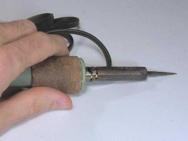
Use a soldering iron with a pointy tip since you'll be working with small parts that are close together.
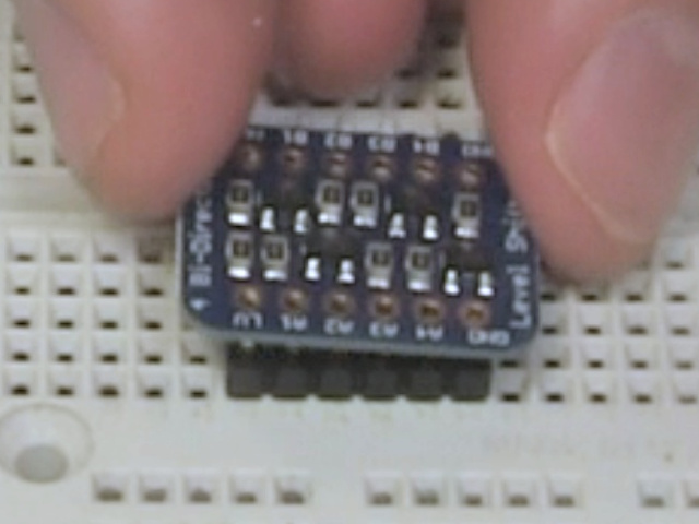
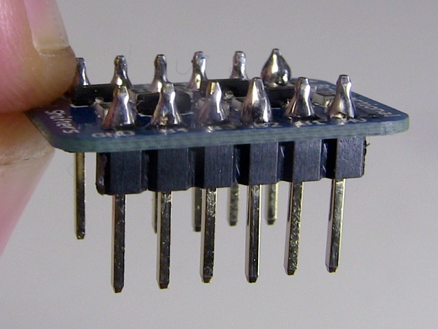
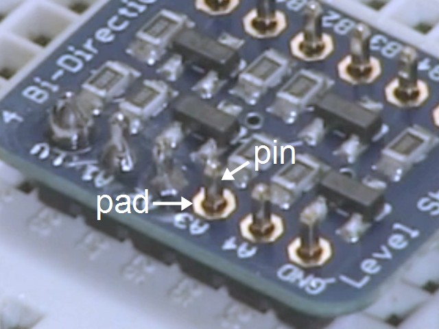
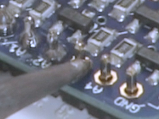
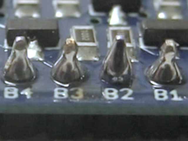
As shown below, the goal is to solder the circular metal pad on the board to the pin. First briefly heat up the pad and pin with the soldering iron, only for a second or so. Then apply a little solder. If things are hot enough then the solder will move to the parts right away, so you'll only touch it briefly.
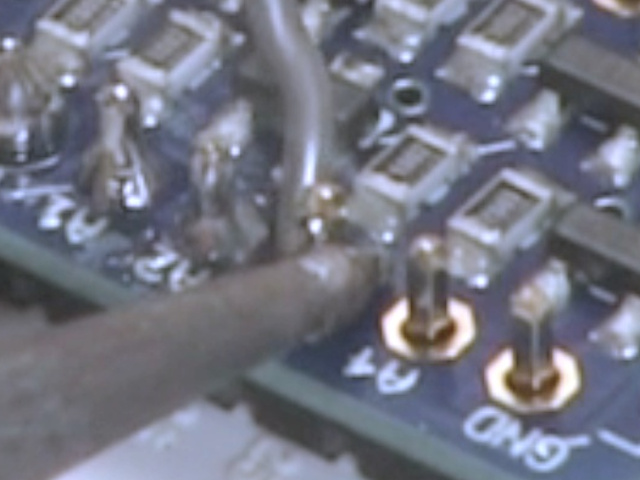
The result should be a cone-shaped bit of solder covering both the circular pad and the bottom part of the pin. There should not be any solder connecting two pins together.
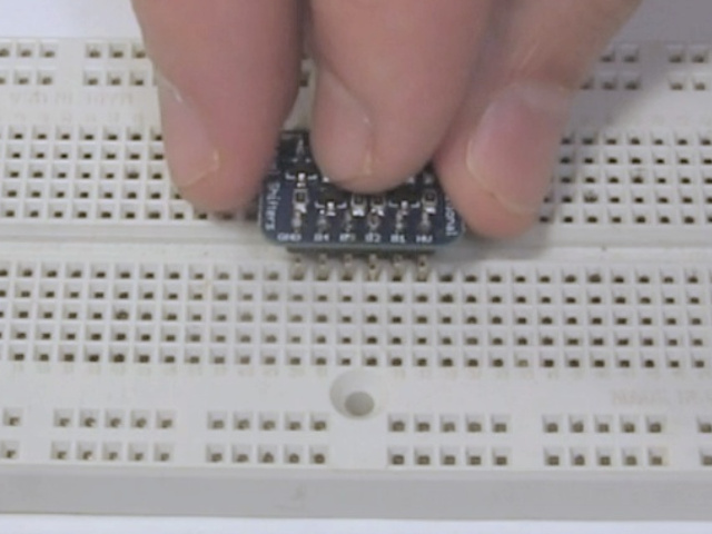
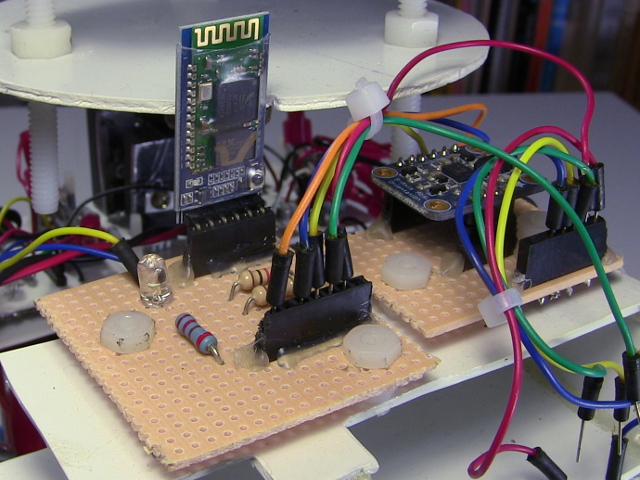
At that point you can insert it into a breadboard or female pin headers that are in another board. Both those approaches make it so you can remove the board if you want to replace it or use it for something else. You can also insert it into a perfboard and start soldering directly to the pins if you want to.
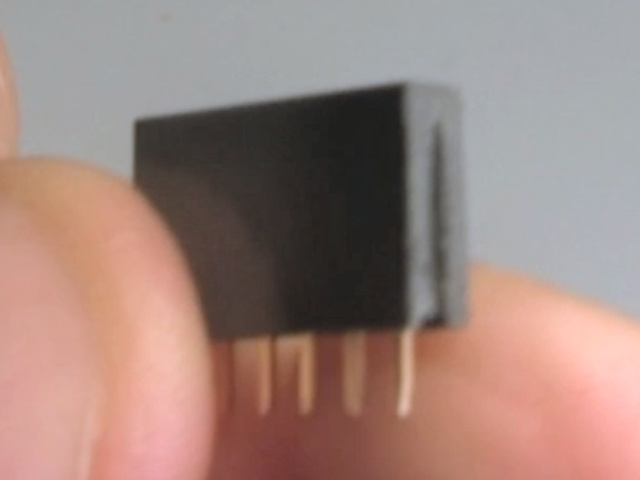
Female pin headers
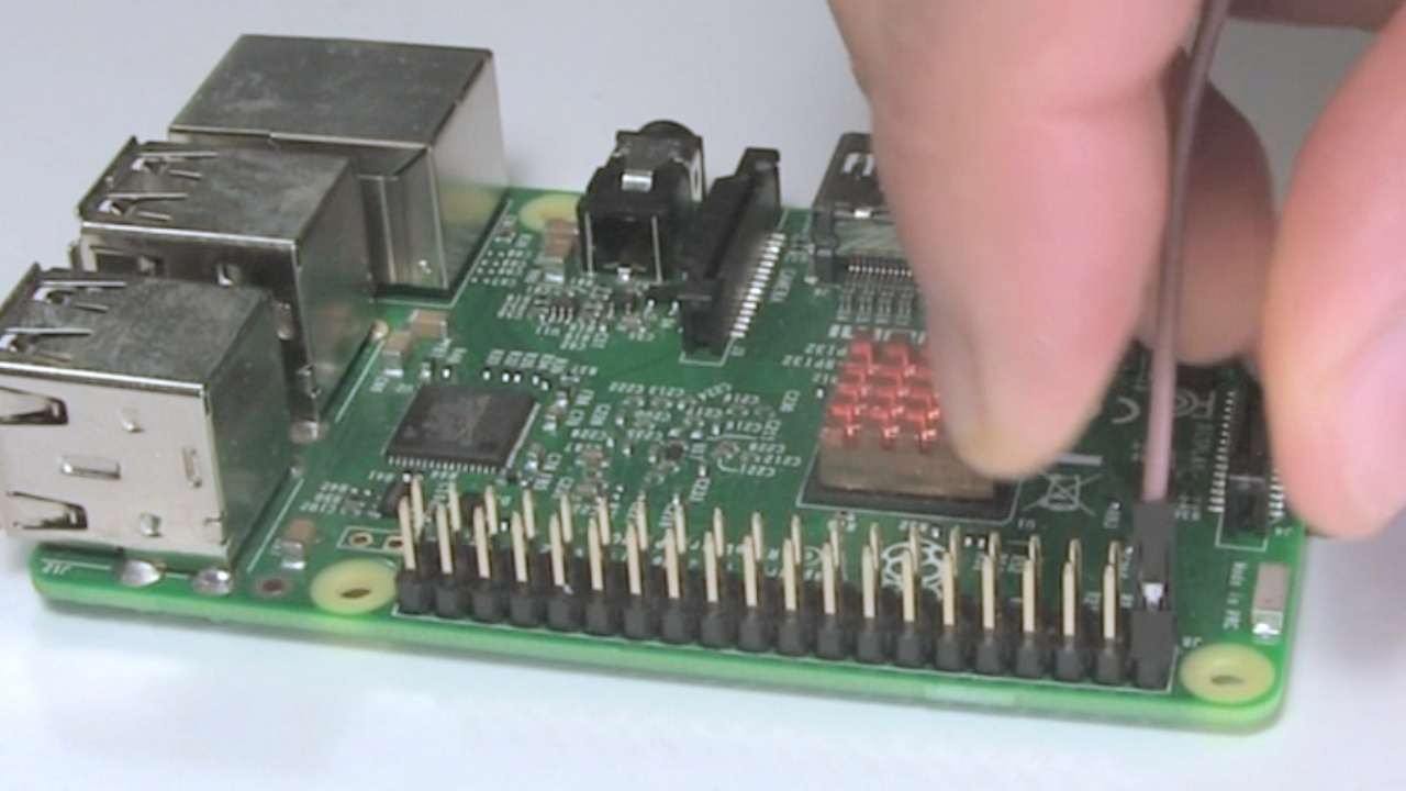
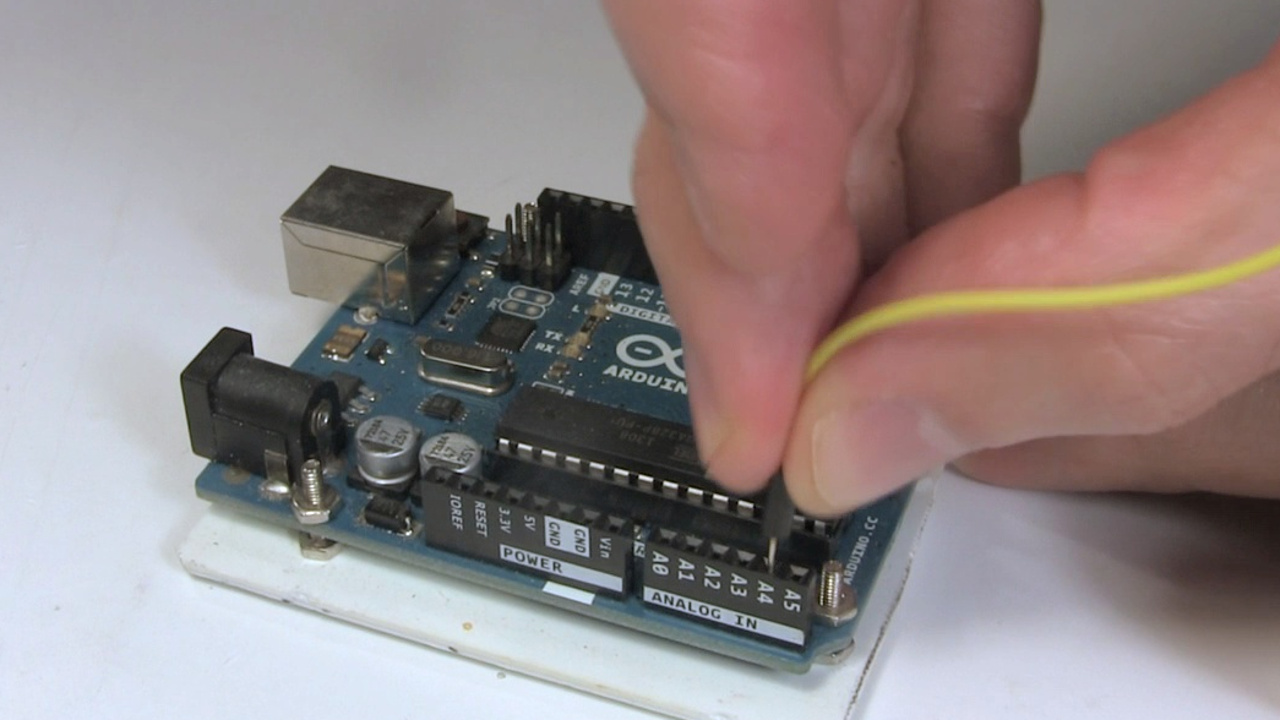
Female pin headers are used when you have a board and you'll either want to plug another board into it, or use jumper wires to connect to another board.
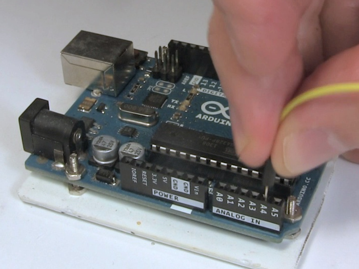
One thing to keep in mind is that you have the right pin headers for the job. The spacing between the pins is important. In the example shown here they are 0.1 inches/2.54mm apart. That's important when you'll be pluging a board into them, as shown in the examples here. You need to use the same spacing as those boards.
You can buy pin headers from places like ebay.com, Adafruit.com, and sparkfun.com.
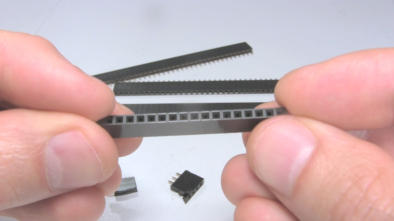
Cutting pin headers
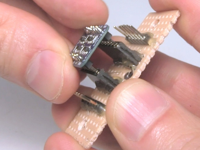
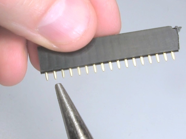
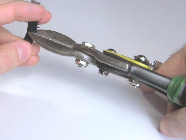
A female pin header has a hole for plugging things into, but on the other side is a pin sticking out. To cut a female pin header, first count out how many holes you need and use a set of pliers to firmly grip the pin that lines up with the next hole after the last one you need. Pull that pin out. You'll actually end up pulling out a fork.
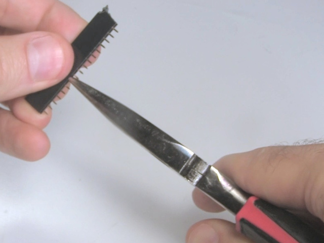
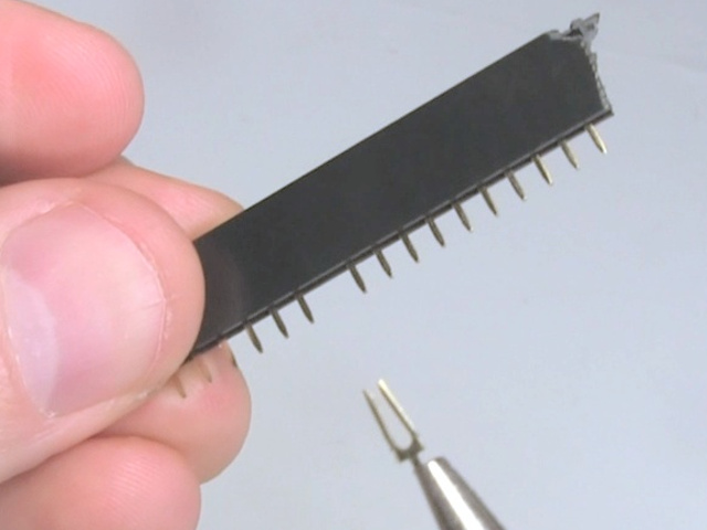
That leaves a pin header with a hole that has no corresponding pin. Make your cut through that hole. In this case I'm using a set of tin snips. Some people cut with a sharp knife.
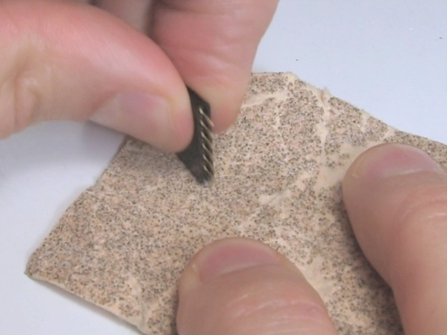
Then clean up the end which you've cut. Use a knife, sandpaper, a file, or whatever you have for this.
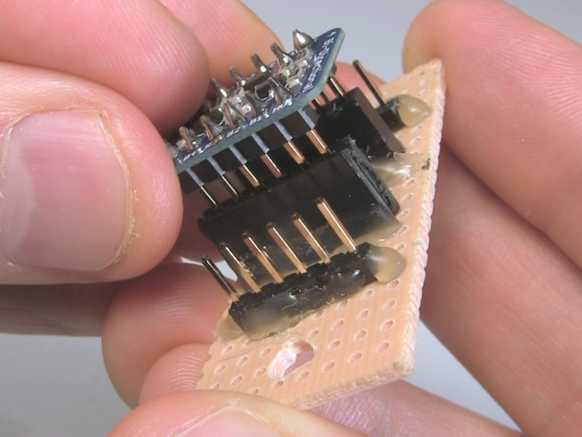
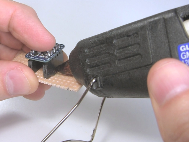
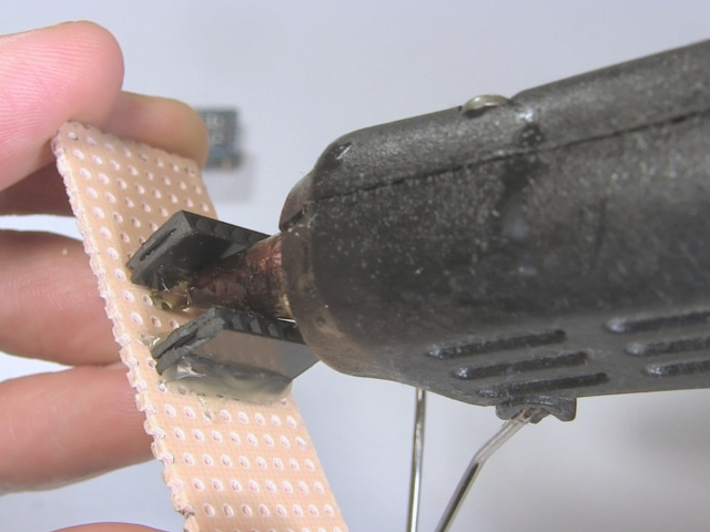
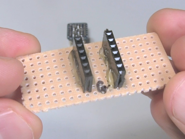
At this point you have a pin header of the right length that you can hot glue or epoxy to a perfboard of some short. It's a good idea when placing the pin headers in the perfboard to have the circuit board that will be used with the pin header inserted into the pin headers, to make sure they're straight. If your perfboard is one that you can solder to then you can solder the pins to the perfboard to hold it in place.
Video - Pin Headers - soldering, cutting, male, female, etc.
This video walks though working with pin headers, showing how to solder male pin headers and how to cut female pin headers and more.
