Servo motors using Raspberry Pi and Pololu Maestro controller board
Here's how to control servo motors with a Raspberry Pi 3 and the Pololu Maestro controller board. Also included is a python module containing functions for most of the motor controls (some weren't needed). The libraries may work with earlier versions of the Raspberry Pi too but haven't been tested.
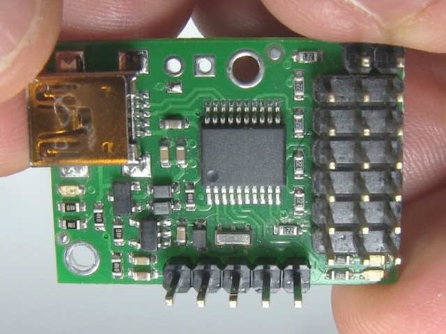
This uses what Maestro calls UART mode. In that mode the Pi talks to the Maestro using the serial TX and RX pins. The code has been tested only with the Micro Maestro 6-Channel USB Servo Controller.
Why use a motor controller instead of controlling directly from the Raspberry Pi? The Linux operating system running on Raspberry Pi is not a realtime operating system, meaning that it's hard to do precise motor control with it -- other things running on the Pi can interrupt. With the controller board, you can tell it:
- the acceleration,
- the speed to run the motor at, and
- the position that you want the servo motor to rotate to.
It will then accelerate the motor to the desired speed and make it rotate to the desired position all without involving the Raspberry Pi, and more importantly, all with being interfered with by anything running on the Pi.
Another approach is to use something like an Arduino using a servo library as the dedicated motor controller instead of the Maestro.
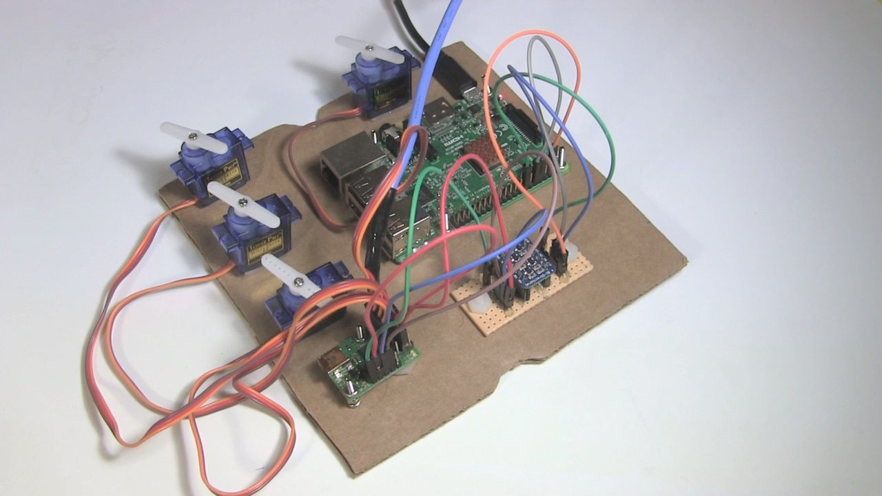
The circuits
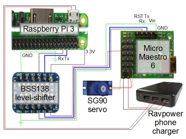
Below is a circuit diagram for controlling servo motors using the Raspberry Pi 3 and the Pololu Maestro controller board.
Communicating between the Pi and the Maestro
The Maestro uses TTL logic, i.e. 5 volts, for the transmit (TX) and receive (RX) signals whereas the Pi uses 3.3 volt logic. As such, a level-shifter is needed between the two in order to convert the voltages for each board. In this case, we're using the BSS138 level-shifter from Adafruit.
Note that some have reported being able to get it to work without a level-shifter. I've tried it but found that the Maestro faults after only a sending a few commands between them.
Power options
For one of my applications, a very compute intensive one with a Pi Camera 2 and two servos, I've found that if the 5V at the level-shifter and Maestro board is around 5.0V then the Maestro can go into a fault mode (the red LED stays on) and communicating with it fails. Around 5.2V seems fine though.
For that same applicaiton, I also found that if the 3.3V side of the level-shifter is around 3.29V then the Maestro can go into a fault mode (the red LED stays on) and communicating with it fails. Around 3.3V seems fine though.
This means that depending on your application, you may need to try different power sources and wiring schemes (circuit diagrams below). For example, when powering from my old desktop Gateway computer's USB ports, the voltages were high enough. But the Ravpower mobile phone charger wasn't able to provide sufficient voltages. Even powering the Pi using a 5.25V/2.4A rated wall adapter while powering the Maestro using an Insignia charger which plugs also into the wall socket didn't provide sufficient voltages.
Besides trying different power sources, you can also play around with where the Maestro and the 5V side of the level-shifter get their 5 volts from. They can get it either from the Pi's 5V pin or from the servo motor's power source. The following two diagram show these different wiring schemes. The diagram further above does it using the latter approach.
Taking 5V from the Pi.
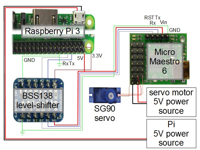
The above approach, having the 5V side of the level-shifter and the Maestro board both take their 5V from the Pi, is pretty straight-forward. Note that it means that the Pi has to be able to supply enough power for both without the voltage dropping too low.
Taking 5V from the servo motor source
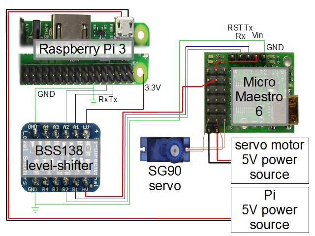
In the circuit above, the servo motors, the 5V side of the level-shifter, and the Maestro board are all being powered by the same 5V source as the servo motors. The Pi is powered separately. This means that not as much power goes needlessly through the Pi. But it also means that if your servos are working hard or you have many of them then the voltage may drop too low and the Maestro may fault.
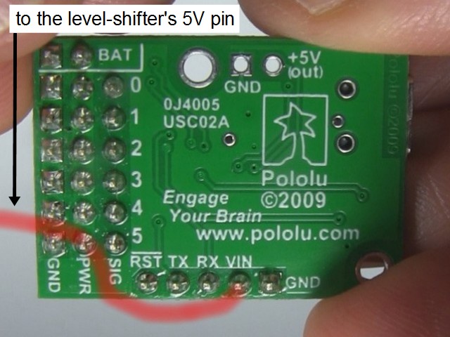
The two grounds of the level-shifter are common, and so with the way the wiring is done here, all grounds are common. The leftmost row of pins on the Maestro in the diagram are also ground pins and are electrically connected to the pin that's shown as GND.
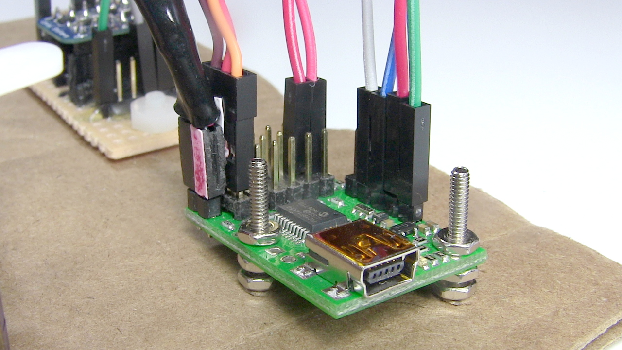
Notice that the power from the servo power source is plugged into two pins labeled BAT on the underside of the board (see photo below), located below the column of connectors for the six servo motors. Those two pins are electrically connected to the left and center pins for each servo motor, labeled GND and PWR on the underside of the board (see photo below). To have that power also go to the rest of the Maestro board, we need to connect the Vin pin to any of the center pins, the PWR pins (see photo below). This is usually done by soldering a wire between them as shown. The same can be done to power the 5 volt side of the level-shifter. However, since I wasn't using all four servo motor connectors, I just used jumper wires to connect them without doing the soldering underneath.
The Maestro's reset pin
In the circuit diagrams, RST refers to the reset pin which I haven't had a need for. To reset it, you briefly pull the RST line low i.e. to GND.
I have tried it out though. To do so I connect a jumper to the Maestro's RST pin and then manually connect the other end of the jumper to a spare GND (ground) pin on the Pi. The LEDs on the Maestro all turn off and when you remove the jumper from the Pi's GND, the LEDs turn on again. However, if software on the Pi had the serial port open and was communicating at the time, the software doesn't seem to recover.
So this is best done under software control so that the software can recover after the reset. The Maestro manual talks briefly about doing this by connecting it to one of the Pi's GPIO pins and having it normally high (5V) and then briefly driving it low (0V) to do the reset.
The Maestro phyton module - maestro_uart.py
Below is the source code for a python module (tested with python 3) containing many of the functions needed for using the Maestro. Extensive comments in the module tells you how to use each function. They are also documented further below.
maestro_uart.py- 6K, plain text python source file
"""
Pololu Maestro servo controller board library
"""
import serial

class MaestroUART(object):
	def __init__(self, device='/dev/ttyS0', baudrate=9600):
		"""Open the given serial port and do any setup for the serial port.

		Args:
			device: The name of the serial port that the Maestro is connected to.
				Default is '/dev/ttyS0'.
				Examples: "/dev/ttyAMA0" for Raspberry Pi 2, "/dev/ttyS0" for
				Raspberry Pi 3.
			baudrate: Default is 9600.
		"""
		self.ser = serial.Serial(device)
		self.ser.baudrate = baudrate
		self.ser.bytesize = serial.EIGHTBITS
		self.ser.parity = serial.PARITY_NONE
		self.ser.stopbits = serial.STOPBITS_ONE
		self.ser.xonxoff = False
		self.ser.timeout = 0 # makes the read non-blocking

	def get_error(self):
		"""Check if there was an error.

		Returns:
			>0: error, see the Maestro manual for the error values
			0: no error, or error getting the position, check the connections,
			could also be low power
		"""
		command = bytes([0xAA, 0x0C, 0xA1 & 0x7F])

		self.ser.write(command)

		data = [b'\x00', b'\x00']
		n = 0
		while n != 2:
			data[n] = self.ser.read(1)
			if not data[n]: continue
			n = n + 1

		return int.from_bytes(data[0], byteorder='big') & 0x7F + (int.from_bytes(data[1], byteorder='big') & 0x7F) << 7

	def get_position(self, channel):
		"""Gets the position of a servo from a Maestro channel.

		Args:
			channel: The channel for the servo motor (0, 1, ...).

		Returns:
			>0: the servo position in quarter-microseconds
			0: error getting the position, check the connections, could also be
			low power
		"""
		command = bytes([0xAA, 0x0C, 0x90 & 0x7F, channel])

		self.ser.write(command)

		data = [b'\x00', b'\x00']
		n = 0
		while n != 2:
			data[n] = self.ser.read(1)
			if not data[n]: continue
			n = n + 1

		return int.from_bytes(data[0], byteorder='big') + 256 * int.from_bytes(data[1], byteorder='big')

	def set_speed(self, channel, speed):
		"""Sets the speed of a Maestro channel.

		Args:
			channel: The channel for the servo motor (0, 1, ...).
		 	speed: The speed you want the motor to move at. The units of
				'speed' are in units of (0.25us/10ms). A speed of 0 means
				unlimited.

		Example (speed is 32):
		Let's say the distance from your current position to the target
		is 1008us and you want to take 1.25 seconds (1250ms) to get there.
		The required speed is (1008us/1250ms) = 0.8064us/ms.
		Converting to units of (0.25us/10ms),
		0.8064us/ms / (0.25us/10ms) = 32.256.
		So we'll use 32 for the speed.

		Example (speed is 140, from the Maestro manual):
		Let's say we set the speed to 140. That is a speed of
		3.5us/ms (140 * 0.25us/10ms = 3.5us/ms). If your target is such that
		you're going from 1000us to 1350us, then it will take 100ms.

		Returns:
			none
		"""
		command = bytes([0xAA, 0x0C, 0x87 & 0x7F, channel, speed & 0x7F, (speed >> 7) & 0x7F])
		self.ser.write(command)

	def set_acceleration(self, channel, accel):
		"""Sets the acceleration of a Maestro channel. Note that once you set
		the acceleration, it will still be in effect for all your movements
		of that servo motor until you change it to something else.

		Args:
			channel: The channel for the servo motor (0, 1, ...).
			accel: The rate at which you want the motor to accelerate in
				the range of 0 to 255. 0 means there's no acceleration limit.
				The value is in units of (0.25 us)/(10 ms)/(80 ms).

		Example (acceleration is ):
		Let's say our motor is currently not moving and we're setting our
		speed to 32, meaning 0.8064us/ms (see the example for set_speed()).
		Let's say we want to get up to that speed in 0.5 seconds.
		Think of 0.8064us/ms as you would 0.8064m/ms (m for meters) if you
		find the 'us' confusing.
		Step 1. Find the acceleration in units of us/ms/ms:
		accel = (Vfinal - Vinitial) / time, V means velocity or speed
		Vfinal = 0.8064us/ms
		Vinitial = 0us/ms (the motor was not moving to begin with)
		time = 0.5 seconds = 500ms
		Therefore:
		accel = (0.8064us/ms - 0us/ms) / 500ms = 0.0016128us/ms/ms
		Step 2. Convert to units of (0.25 us)/(10 ms)/(80 ms):
		0.0016128us/ms/ms / [(0.25 us)/(10 ms)/(80 ms)] =
		0.0016128us/ms/ms / 0.0003125us/ms/ms = 5.16096
		So we'll set the acceleration to 5.

		Example (acceleration is 4, from the Maestro manual):
		A value of 4 means that you want the speed of the servo to change
		by a maximum of 1250us/s every second.
		4 x 0.25us / 10ms / 80ms = 0.00125us/ms/ms,
		which is 1250us/s/s.

		Returns:
			none
		"""
		command = bytes([0xAA, 0x0C, 0x89 & 0x7F, channel, accel & 0x7F, (accel >> 7) & 0x7F])
		self.ser.write(command)

	def set_target(self, channel, target):
		"""Sets the target of a Maestro channel.

		Args:
			channel: The channel for the servo motor (0, 1, ...).
			target: Where you want the servo to move to in quarter-microseconds.
				Allowing quarter-microseconds gives you more resolution to work
				with.
				Example: If you want to move it to 2000us then pass
				8000us (4 x 2000us).

		Returns:
			none
		"""
		command = bytes([0xAA, 0x0C, 0x84 & 0x7F, channel, target & 0x7F, (target >> 7) & 0x7F])
		self.ser.write(command)

	def close(self):
		"""
		Close the serial port.

		Args:
			none

		Returns:
			none
		"""
		self.ser.close();

if __name__ == '__main__':
	# min_pos and max_pos are the minimum and maxium positions for the servos
	# in quarter-microseconds. The defaults are 992*4 and 2000*4. See the Maestro
	# manual for how to change these values.
	# Allowing quarter-microseconds gives you more resolution to work with.
	# e.g. If you want a maximum of 2000us then use 8000us (4 x 2000us).

	min_pos = 992*4
	max_pos = 2000*4

	mu = MaestroUART('/dev/ttyS0', 9600)
	channel = 0

	error = mu.get_error()
	if error:
		print(error)

	accel = 5
	mu.set_acceleration(channel, accel)

	speed = 32
	mu.set_speed(channel, speed)

	position = mu.get_position(channel)

	print('Position is: %d quarter-microseconds' % position)

	if position < min_pos+((max_pos - min_pos)/2): # if less than halfway
		target = max_pos
	else:
		target = min_pos

	print('Moving to: %d quarter-microseconds' % target)

	mu.set_target(channel, target)

	mu.close()
The functions
The module contains a class called MaestroUART. When you create an instance of it, you pass the name of the serial port and the baud rate. On a Raspberry Pi 3 the RX and TX pins are accessed through the device /dev/ttyS0 (that's a zero, not the letter O). On Raspberry Pi 2 it was /dev/ttyAMA0. The Maestro board's factory default is to detect the baud rate. Creating an instance of the MaestroUART module opens the servial port.
get_error()
Check if there was an error.
Arguments:
none
Returns:
>0: error, see
section 4.e. of the Maestro manual for the error values
0: no error, or error getting the position, check the connections,
could also be low power
get_position(self, channel)
Gets the position of a servo from a Maestro channel.
Args:
channel: The channel for the servo motor (0, 1, ...).
Returns:
>0: the servo position in quarter-microseconds
0: error getting the position, check the connections, could also be
low power
set_speed(self, channel, speed)
Sets the speed of a Maestro channel.
Args:channel: The channel for the servo motor (0, 1, ...).
speed: The speed you want the motor to move at. The units of 'speed' are in units of (0.25us/10ms). A speed of 0 means unlimited.
Example (speed is 32):
Let's say the distance from your current position to the target is 1008us and you want to take 1.25 seconds (1250ms) to get there. The required speed is (1008us/1250ms) = 0.8064us/ms. Converting to units of (0.25us/10ms), 0.8064us/ms / (0.25us/10ms) = 32.256. So we'll use 32 for the speed.
Example (speed is 140, from the Maestro manual):
Let's say we set the speed to 140. That is a speed of 3.5us/ms (140 * 0.25us/10ms = 3.5us/ms). If your target is such that you're going from 1000us to 1350us, then it will take 100ms.
Returns:
none
set_acceleration(self, channel, accel)
Sets the acceleration of a Maestro channel. Note that once you set the acceleration, it will still be in effect for all your movements of that servo motor until you change it to something else.
Args:
channel: The channel for the servo motor (0, 1, ...).
accel: The rate at which you want the motor to accelerate in
the range of 0 to 255. 0 means there's no acceleration limit.
The value is in units of (0.25 us)/(10 ms)/(80 ms).
Example (acceleration is 5):
Let's say our motor is currently not moving and we're setting our
speed to 32, meaning 0.8064us/ms (see the example for set_speed()).
Let's say we want to get up to that speed in 0.5 seconds.
Think of 0.8064us/ms as you would 0.8064m/ms (m for meters) if you
find the 'us' confusing.
Step 1. Find the acceleration in units of us/ms/ms:
accel = (Vfinal - Vinitial) / time, V means velocity or speed
Vfinal = 0.8064us/ms
Vinitial = 0us/ms (the motor was not moving to begin with)
time = 0.5 seconds = 500ms
Therefore:
accel = (0.8064us/ms - 0us/ms) / 500ms = 0.0016128us/ms/ms
Step 2. Convert to units of (0.25 us)/(10 ms)/(80 ms):
0.0016128us/ms/ms / [(0.25 us)/(10 ms)/(80 ms)] =
0.0016128us/ms/ms / 0.0003125us/ms/ms = 5.16096
So we'll set the acceleration to 5.
Example (acceleration is 4, from the Maestro manual):
A value of 4 means that you want the speed of the servo to change
by a maximum of 1250us/s every second.
4 x 0.25us / 10ms / 80ms = 0.00125us/ms/ms,
which is 1250us/s/s.
Returns:
none
set_target(self, channel, target)
Sets the target of a Maestro channel.
Args:
channel: The channel for the servo motor (0, 1, ...).
target: Where you want the servo to move to in quarter-microseconds.
Allowing quarter-microseconds gives you more resolution to work
with.
Example: If you want to move it to 2000us then pass 8000us (4 x 2000us).
Returns:
none
close(self)
Close the serial port.
Args:
none
Returns:
none
Troubleshooting
maestro_get_position() returning 0
The serial port is opened in non-blocking mode, meaning that it won't block on a read. However, it's been found that if the power going to the Maestro is low then the reads done by the functions that get things from the Maestro (maestro_get_error(), maestro_get_position()) may return with a 0 for that reason. This has been found to happen with the above circuit when powering up to four servos at a time using the RavPower, while the problem goes away when powering from USB ports from a desktop computer.
Maestro python demonstration code - maestro_demo.py
The following code demonstrates the use of the maestro_uart.py module's functions.
maestro_demo.py- 1K, plain text python source file
"""
Demonstration program for the maestro_part library for controlling a
servo motor with the Raspberry Pi 3 and the Pololu Maestro board.
"""

import maestro_uart

# min_pos and max_pos are the minimum and maxium positions for the servos
# in quarter-microseconds. The defaults are set on the board. See the Maestro
# manual for how to change these values. The factory defaults are 992us and
# 2000us.
# Allowing quarter-microseconds gives you more resolution to work with.
# e.g. If you want a maximum of 2000us then use 8000us (4 x 2000us).

min_pos = 992*4
max_pos = 2000*4

mu = maestro_uart.MaestroUART('/dev/ttyS0', 9600)
channel = 0

error = mu.get_error()
if error:
	print(error)

accel = 5
mu.set_acceleration(channel, accel)

speed = 32
mu.set_speed(channel, speed)

position = mu.get_position(channel)

print('Position is: %d quarter-microseconds' % position)

if position < min_pos+((max_pos - min_pos)/2): # if less than halfway
	target = max_pos
else:
	target = min_pos

print('Moving to: %d quarter-microseconds' % target)

mu.set_target(channel, target)

mu.close()
Video - Servo Motor With Raspberry Pi and Maestro board
The following video goes over the circuit, the Pi configuration, and the pyhon code, as well as shows the servo motors being controlled by the Pi and Maestro.
