Testatika Pots (Mk2)

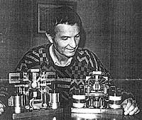
For each of the two small testatika units and the 50cm disk unit there are two canisters, frequently refered to as pots. The contents of these pots are largely unkown. The only person reported to have seen inside was Stefan Marinov and he saw inside only the pots for one of the small units. He said the following:

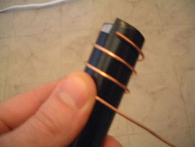
The capacitors have a cylindrical "grid", cylindrical plastic insulation and a copper spiral in the center... THAT'S ALL! I saw in one of the small machines and there are no magnets. - Stefan Marinov 9/4/90

Stefan Marinov with the two small units. Picture from this website.

Further evidence of the presence of grids comes from the report from the visit of 30 engineers to the Methernitha community where near the bottom of the report, the following is said of the 50cm disk unit (the 3kW machine): "In the large capacitors there are 20 layers of perforated sheet (Baumann said)".

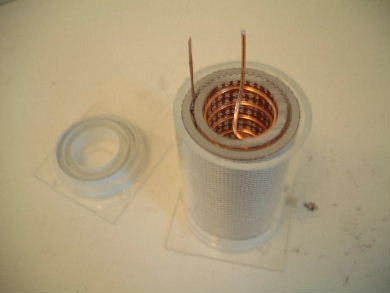
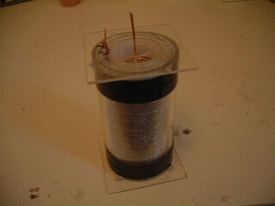
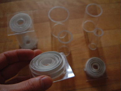
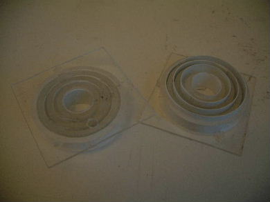
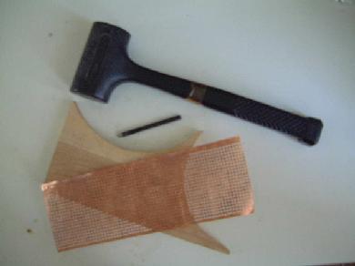
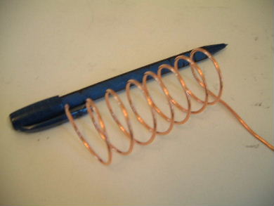
For my various tests I of course needed pots, and I wished to make mine as close to what Stefan Marinov said he saw inside them, namely one or more grids, spaced apart by clear plastic cylinders and with a loose coil of thick wire with a few turns in the middle. I also wanted to make the spacing as precise as I could and the components changable. Note that what is actually used in any one experiment will vary but this will give you an idea of how they can be built.

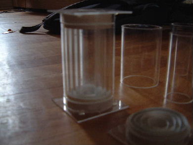
Construction of the Pots

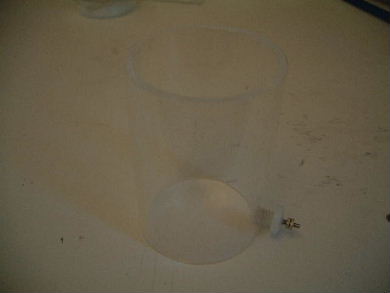
Amazingly, I happened to find a store that had clear acrylic cylinders of the diameters I needed based on my measurements of the small machine from pictures. The heights of all cylinders are 80mm. The remaining diameters are as in the following table.

Description Inner diameter Outer diameter
The outer cylinder which will not have any electrode around it. 50mm 57mm
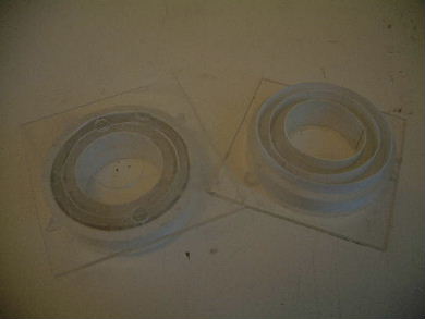
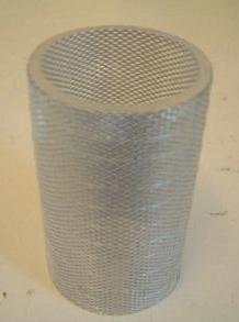
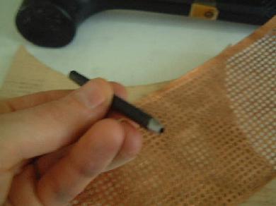
The next cylinder in will have an aluminum grid electrode wrapped around it. 41mm 47mm
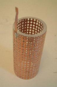
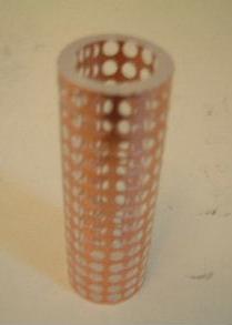
The next cylinder in will be the output cylinder and will have a copper grid electrode wrapped around it. 31mm 38mm
The last cylinder may not be used. 19mm 26mm

The separators are acrylic.
Assembled plastic parts for illustration purposes.
The tops and bottoms hold the cylinders spaced apart the correct amount. The thin white cylinders are thin plastic. These actually hold the taller cylinders in place. They grip the tall cylinders on their inside surface. Here they are configured for holding three tall cylinders.
Here extra parts are added to the middle for holding a fourth cylinder.
The second tall cylinder from the outside has a fine aluminum grid. A thin fishing line can be seen wrapped around the cylinder to hold it in place. The fishing line is tied to a grid hole at the top and another at the bottom.
The third tall cylinder from the outside has a copper grid with 2.5mm holes. This is the output cylinder so has a copper vertical contact strip that stands up.
The fourth tall cylinder from the outside has a copper grid with 4mm holes. This cylinder may not be used.
The above copper cylinders were handmade by first drawing the grid on a sheet of copper and then pounding the holes out with a hole punch and a hardwood backing.
It wasn't as hard or time consuming as you'd think.
The center coil was made by shaping it on the outside of tube of the correct size. The spacing between turns is 1cm. A 1cm wide strip of black tape was first wrapped around the tube to act as a guide for shaping the wire.
The wire for the coil is 14 AWG copper. It was taken from 14/2 household electrical wire. The ground wire was used since it was already stripped.
The resulting coil has 7.5 turns with 1cm between each turn.
The outer electrode is aluminum (see above). To make electrical contact with it a hole was drilled in the outermost cylinder and threaded for a 1/4" bolt. A 1/4" nylon bolt was then cut short and a hole drilled through the center of it. A smaller diameter metal bolt was then pushed through this hole and epoxied in place. Before this, a strip of copper was wrapped around the head of the small metal bolt and soldered added. This was to increase surface area. In this picture, one nylon bolt is shown screwed into the hole in the cylinder and another is sitting beside.
Here's the end result.
The end result with the top off.
The end result fully assembled. Black electrical tape has been added to make sure the top and bottom will not fall off. Sticking out the top on the left of center is the vertical contact strip for making contact with the output cylinder (see the description for one of the copper cylinders above).
rimstar.org
Contact:
Liked this? Share it with: