Testatika Pots (Mk4)

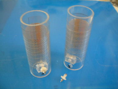
For each of the two small testatika units and the 50cm disk unit there are two canisters, frequently refered to as pots. The contents of these pots are largely unkown. The only person reported to have seen inside was Stefan Marinov and he saw inside only the pots for one of the small units. He said the following:

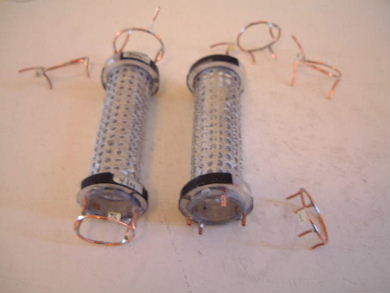
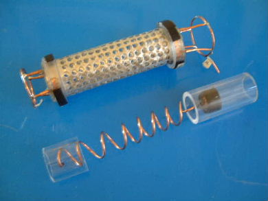
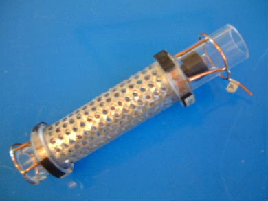
The capacitors have a cylindrical "grid", cylindrical plastic insulation and a copper spiral in the center... THAT'S ALL! I saw in one of the small machines and there are no magnets. - Stefan Marinov 9/4/90

Stefan Marinov with the two small units. Picture from this website.

Further evidence of the presence of grids comes from the report from the visit of 30 engineers to the Methernitha community where near the bottom of the report, the following is said of the 50cm disk unit (the 3kW machine): "In the large capacitors there are 20 layers of perforated sheet (Baumann said)".

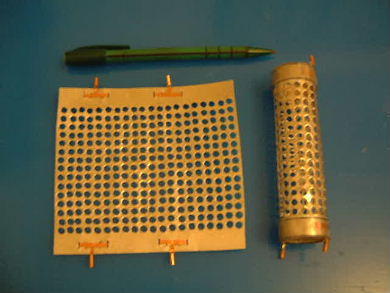
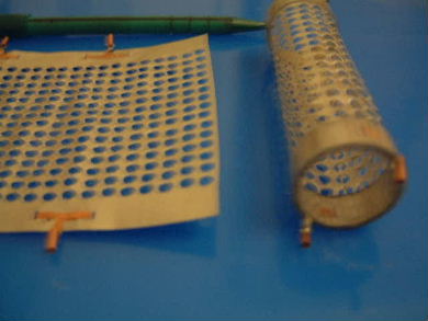
The idea behind these mark 4 pots was primarily to have cylindrical grid cylinders in the middle (i.e. the output ones, not the inner electrode or the outer electrode.) As well, I wanted more flexibility in what could be put in the pots without having to manufacture new ones from scratch all the time.

I wanted to try output grids which were much closer together. In the case below that is ones that were less than one hole/perforation diameter apart.

Construction of the Pots

The one on the left is fully assembled. In the middle is the inner electrode (in this case, a loose coil with a rounded top for spark gap testing) along with the middle grid cylinders. On the right is the outer electrode.
The middle grid cylinders are constructed of stainless steel perforated sheets made from scratch (see below.) They can be electrically connected to at bottom and/or top. The bottom connection allows for connecting them in series to provide a longer electron path should that prove beneficial. Acrylic strips are wrapped around the ends to provide insulation from one grid cylinder to the next.
Another view.
Various combinations of connection schemes are possible using different wire connectors.
On the bottom/right is a loose coil electrode with a rounded top for spark gap testing. Note also that when inserted into the middle grid cylinder (top/left) there would be no insulation between the coil and the innermost grid cylinder. This is optional as the coil can also be inserted into a fullying insulating tube.
An inner electrode inserted into the grid cylinders.
The outer electrodes, grid cylinders. Note the parts for electrically connecting to them.

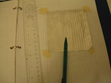
Making grids from scratch

A grid outline is first drawn on paper for the desired hole size. Then the metal sheet is taped to the paper and the rectangular grids drawn onto the metal.
A drill press works great, fast and quietly for making the holes.
The punch in inserted into the drill press's chuck where the drill bit would normally go. The metal and hardwood backing are placed such that the punch will make a hole in a grid space. It is then carefully lowered and pressed through the metal. After four or five holes, the punch is emptied by poking a stiff wire through it. A complete grid like this takes less than an hour to punch.
rimstar.org
Contact:
Liked this? Share it with: