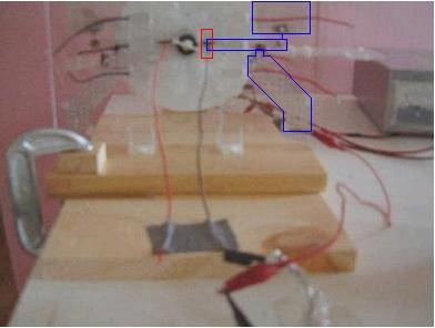
Warning: All test measurements were done incorrectly due to lack of experience using an oscilloscope with a floating voltage source (i.e. where neither electrode is grounded) - one electrode was always being grounded. As a result this information is useful for seeing how the device was constructed and the measurements are useful for historical reference only.
Three sets of tests are shown below for April 20-21:
- Measuring voltage between front-center grid and back grids
- Measuring voltage between front-center grid and front-side grid
- Measuring voltage between front-side grid and back grids
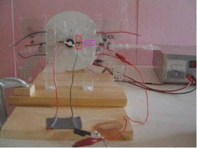
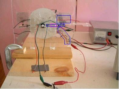
For a clear picture of what grids are where, see the contruction page and look at the pictures up to April 18.
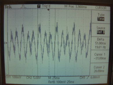
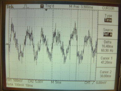
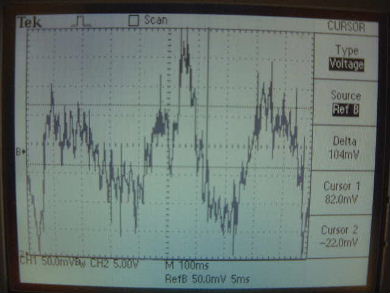
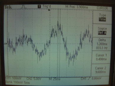
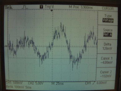
Note that for all tests there was also a 200mV AC signal from the household powerlines present. This affects what you see in the scope shots below. Note also that the disk was rotated at approximately 2400 RPM for all tests. This means that the disk was rotating at 40Hz and that the grids would see the wires at 800Hz (there are 20 wires).
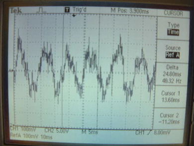
1. Measuring voltage between front-center grid and back grids
|
|
| ||
|
|
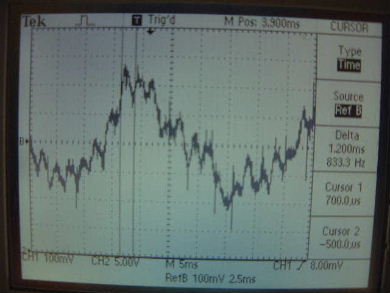
2. Measuring voltage between front-center grid and front-side grid
|
|
|
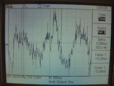
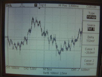
3. Measuring voltage between front-side grid and back grids
|
|
|
|