A series of tests were done to determine the voltage waveforms of the
various grids around the disk circumference in order to determine their
purpose.
In many of the oscilloscope shots below, and especially the traces from the
back grids, the main wave is the 60Hz sine wave coming from household wiring.
Previous measurements, for testbed 1, were done using the
oscilloscope probes incorrectly for a floating voltage source. These
are done correctly.
C-Shaped vs. Flat facing grids
The grids on the sides that face the disk in the testatika small machine
are C-shaped, where the two ends of the C are facing the disk and the
flat part is further away. Seeing that not much voltage was being
gotten out this way, the grids were flattened completely so that all
of it would be close to the disk. Higher voltages were obtained that way.
All the remaining measurements are made with flat facing grids.
Variable capacitor testing
The following measurements were made. Details follow in the pictures below.
Conclusions are mixed in with the details.
- Measuring voltages at front-side grid and back grids
- Measuring voltages at left and right front-side grids
1. Measuring voltages at front-side grid and back grids
The following results clearly show the behaviour of this disk arrangement
as a set of variable capacitors. Note that two additional findings were
particularly important:
- The closer the front and back grids were together, the higher
the voltage.
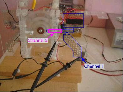
- The back grid is composed of four separate pieces connected together
by direct contact and by wiring (the following picture shows three
of these pieces outlined in blue; the fourth is the bottom diagonal
grid which is not outlined). The lower the resistance between all
the connections, the higher the voltages for both back and front grids.
Each waveform is measured with respect to ground. The
two waveforms are practically mirror images of
each other (taking into account that the top one is riding on interference
from household wiring). This makes sense if they are really opposing
electrodes from the same capacitor.
 |
|
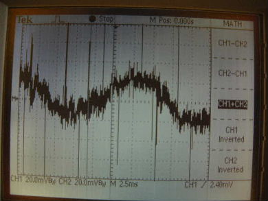
Here the two waveforms on the left are added together
which shows what they are like with respect to each other. The result is
practically only that from the interfering household wiring.
 |
|
The above waveform matches the one shown here,
obtained by another group. Each wire on my disk plays the same part as
one half of their lamela. It is easier to see the waveform for a single pass
by the pickup grids in their pictures since they had only one lamela and
mine had 20 wires. Note also that they saw the same effect
whereby the smaller the gap size between the electrodes, the higher the voltage.
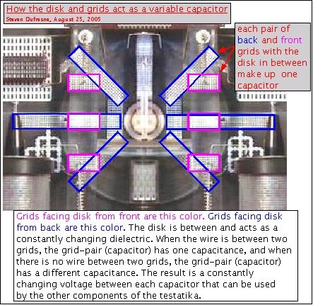
The following explanation uses a picture of the original
testatika. That one and testbed 2 have the same parts for this explanation
and so the testatika being used does not matter.
 |
|
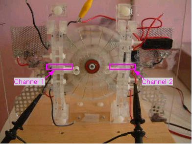
2. Measuring voltages at left and right front-side grids
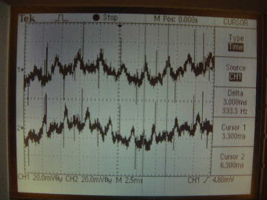
Each waveform is measured with respect to ground.
It may not be perfectly clear but the spikes alternate
from one side to the other.
 |
|
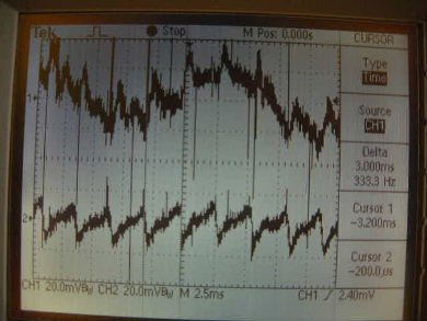
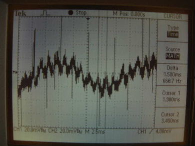
This is especially clear when you add the two waveforms
together. The flat parts cancel and only the spikes show up. The measured
frequency of the spikes on a single waveform in the picture on the left is
333Hz. The frequency of the combined waveform below is 666Hz. So the two
sides are exactly offset from each other by half a wavelength.
 |
|
The reason for the above alternating voltages could be due to the some
interaction across the disk face. Paul Baumann reportedly said that all
the segments of the 3kW machine were connected at the middle with 100 watt
resistors. Could this have been to limit interaction across the disk?
In all photos of the small machine, the ends of the wires when they reach
the middle of the disk are not visible. Could they be connected at the
center via a high resistance ring?
Another possibility is something to do with the fact that the two sides
in this small machine are not really symmetrical when the direction
of the disk rotation is taken into account. On one side the disk is descending
and on the other side it is ascending. As it descends, the order
in which it encounters the grids is reversed with respect to the
order in which it encounters the grids when it ascends.
This remains a mystery.