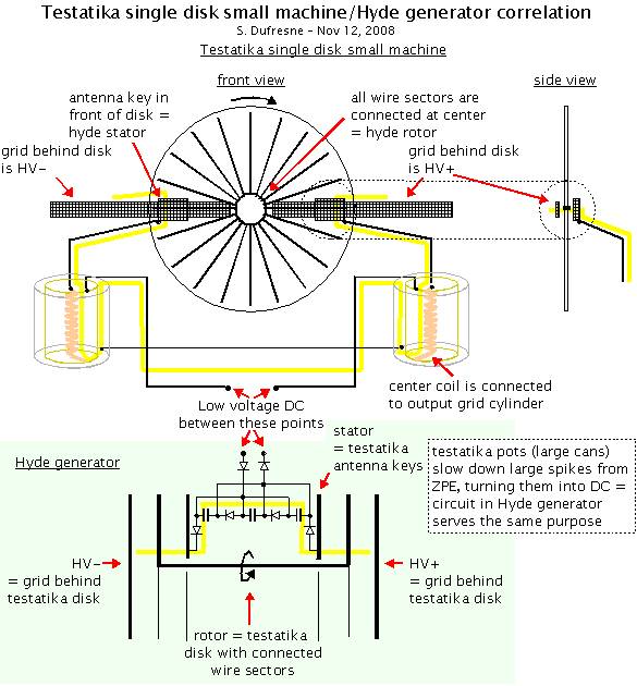
There is a strong correlation between the testatika and the Hyde generator, especially if the disk is assumed to be the source of the excess output. The Hyde generator is a device developed by William W. Hyde that is documented fairly well in US patent 4897592 - Electrostatic energy field power generating system. It produces more energy out than is used to drive the motor that turns it, obviously tapping into an energy source from somewhere else. The energy occured in anomalously large high voltage spikes across the stators where there shouldn't have been any. He used a diode and capacitor circuit to turn these spikes into DC. From private correspondance between William Hyde and Moray B. King1, a prototype that contained 2000 capacitors and diodes produced the following results:
| No. rotor segments | 240 |
| No. stator segments | 480 |
| Rotor speed | 6000 rpm |
| Output voltage | 602 VDC |
| Output current | 38 amps |
| Output power | 22.9 kW |
| Input power | 2.4 kW |
| Net output power (while free running) | 20.5 kW |
|
Here's how they correlate:
- Follow the electric field lines from HV- to HV+ (use the yellow line in the
above diagram.) Both go from:
1. HV- plate/grid through
2. rotor/disk to
3. stator/antenna key through
4. mechanism to slow down anomalous HV spikes (diode & capacitor circuit/pots) to
5. other stator/antenna key through
6. rotor/disk to
7. HV+ plate/grid. - Paul Baumann, inventor of the testatika, said that the purpose of the grid material in the pots was to slow down the charge. This makes sense, given that the pots are in the same place in the overall circuit as the Hyde generator's diode & capacitor circuit.
- The Hyde generator has to rotate at at least 6000 RPM to produce the HV spikes whereas the testatika rotates more slowly. However, the Hyde generator has relatively wide stator and rotor segments whereas the testatika has fine grids.
References
1. King, Moray B. Quest for Zero Point Energy. Adventures Unlimited Press, 2001, p. 28


