The testatika has an output circuit consisting of two pots (to
use the same term as the inventor, Paul Baumann) that if combined
are the same as the single cylindrical device in the
designs that have been come up with here
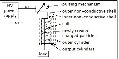
except broken up into two devices. The following diagram is the
original design idea.
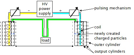
Below is this original design idea but with two coil/cylinders instead
of one. Treating the original coil/cyinder as a capacitor, we simply
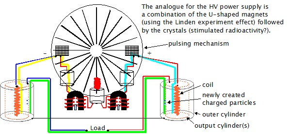
split it into two in series. Below that is the testatika with selected
components and wiring that match.
Some changes have been made to the original design idea here.
Instead of capturing particles of both polarities in a single
coil/cylinder (testatika pot) particles of one polarity are
captured in one and of the other polarity in the other. This
may be done because it may be found that coil windings of opposite
directions when interacting the the electric field may result
in particles of opposite polarity. Or it may be that the output
cylinders need to be coated in such a way as to pick up only
a certain polarity (e.g. cuprous oxide on copper mesh, aluminium
oxide on aluminium mesh.) It may also be possible that there is
a permanent magnet cylinder in the middle of the coil and that
it may be oriented in opposite ways in the two coils, possibly
resulting in particles of opposite polarities being created.
Note also the the original design called for ions to be produced
from the newly created charged particles and for these ions to
be attracted to either of the two output cylinders. Given that
there is only one polarity coming from each pot in the testatika,
it is more likely that either the charged particles are picked up
directly by the output cylinder that created them or that ions are
produced and picked up by those same cylinders.
Given the low capacitance of the coil/cylinder capacitors a relatively
powerful voltage source may be needed.
Such a source may be found in the testatika. We know that the
Linden experiment used
a magnet to demonstrate how to get a high voltage from a magnet
that is stimulated by some high frequency. The U-shaped magnets
and their corresponding parts may be using just this mechanism
with initial stimulation coming from the hand-turned disks. It
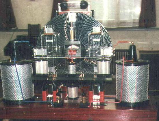
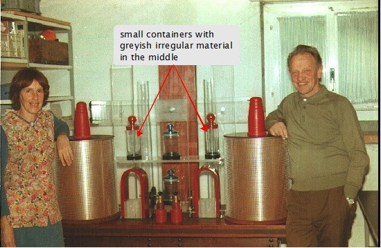
is inferred that the outer legs of these magnets are wired to the
bottom of the smaller pots just above them (see photo below.)
These smaller pots may contain, amoung other needed things,
mountain crystals which may be seen in other unfinished versions
of the testatika (see second photo below.) With the charge
coming from the Linden experiment magnet components and the
action of the disks, stimulated radioactivity may be going on
with these crystals, providing further charge. The end result
would be sufficient charge and high voltage to supply a sufficient
electric field to the large pots to result in charge particle
creation in the mesh of the output cylinders.