
The following is an example of some very well done electrokinetic experiments similar to those of Thomas Townsend Brown done by John Pietrasik. Thank you to John for sharing this work. All of the following text and diagrams are from him.
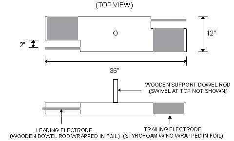
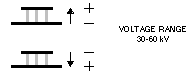
1. Wing-style device (spins around the center)
When energized this device spins in the direction of the leading electrode (i.e., counterclockwise in this diagram). Strong thrust is noticed when the leading electrode is made positive with respect to the trailing electrode. The thrust is greatly reduced when the ends of the leading electrode are covered with electrical tape. No thrust was observed when the polarity was reversed (i.e., leading electrode negative).
|
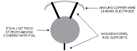
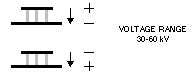
2. Standard (T.T. Brown) disk/leading wire style device
When energized this device exerts a thrust towards the leading electrode regardless of the polarity. The strongest thrust occurs when the leading electrode is made positive with respect to the disk electrode. When the polarity is reversed, the thrust is significantly reduced. Covering the ends of the leading electrode with electrical tape significantly reduces the thrust when the leading edge is positive.
See below for a description of the balance used for this experiment.
|
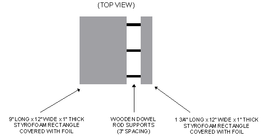
3. Thick disk/leading electrode device
All corners and edges of this device's styrofoam were carefully sanded to eliminate any sharp points. This was to prevent the formation of corona (and thus ion-wind). Thrust was always in the direction of the leading electrode regardless of polarity, but was always very weak.
See below for a description of the balance used for this experiment.
|
Additional electrokinetic experiments (04/04/2000)
The basic device used for these experiments was constructed as follows:
|
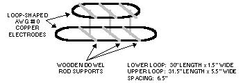
As shown, it is constructed of two loop-shaped copper electrodes held in place by wooden dowel-rod supports. The ends of the loops were carefully soldered together so that the loops surfaces were smooth. This was an attempt to minimize corona by eliminating any sharp points on the electrodes. This device was attached to my simple beam-balance with the small loop facing upwards as drawn. Although I could not measure the thrust, the beam-balance gave a visible means of determining the thrust direction. Several test methods were then performed.
1. Uncovered electrodes
The device was energized with the electrodes uncovered. This yielded the following results (polarity is indicated as well as thrust direction).
|
The thrust appeared to be proportional to voltage and always in the direction of the positive. When operated in the dark, there was visible corona at the curved ends of the loops.. This lead me to the conclusion that the thrust resulted mainly from ion-wind.
2. Electrodes insulated with paper and electrical tape
For this test, the loop electrodes were covered with 8.5" x 11" sheets of plain paper wrapped into 1" O.D. tubes. Standard electrical tape was used to hold these tubes together and cover any areas where the copper loops were visible. The idea was that any generated ions would be confined inside the tubes thus preventing ion-wind thrust. According to T.T. Brown's patent #3187206, a parallel plate capacitor with unequal size plates should always exhibit thrust towards the larger plate, regardless of polarity. This is exactly what was observed with this setup (see below), although the thrust was significantly lower.
|
3. Conclusions
There is strong evidence to indicate that the thrust as described by T. T. Brown's patent does exist. This thrust is in the direction of high flux density to low flux density (i.e., small loop to large loop with this setup). I intend to perform additional experiments to further reduce ambient ionization and hopefully increase the magnitude of this force.
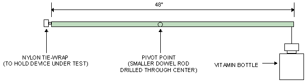
Balance mechanism used for some experiments
The following diagram shows the balance used for some experiments. The plastic vitamin bottle was filled with coins to balance the weight of the attached device. Although actual thrust could not be measured, it was possible to observe even minute amounts of thrust due to length of the balance.
|
|
Do you have a project you'd like to share on rimstar.org too? You're more than welcome to. Click here for details. |
|

