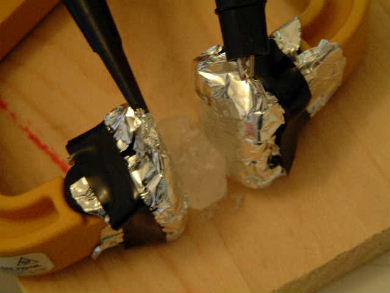
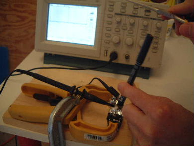
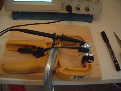
Needing some piezoelectric crystals I decided to make some rochelle salt crystals. I've detailed the steps on my how to make rochelle salt crystals page. Once I had a crystal I then proceeded to test its piezoelectricity as detailed below. Note that this test procedure can be used with pretty much any type of piezoelectric crystal.

Selected piezoelectric rochelle salt crystal in test position.
I selected what looked like my largest single crystal and wedged it lightly between two electrical contact surfaces. The surfaces were made by packing layers of paper towel behind aluminum foil. This gave me an aluminum foil cushion. This allowed me to press both sides of the crystal with these cushions, resulting in good electrical contact without putting too much pressure on the crystal.
Piezoelectric rochelle salt crystal test setup.
To do the test, I placed the flat end of a plactic bodied marker on the crystal surface and tapped lightly on the other end of the marker with the flat of a pair of pliers.
Oscilloscope output showing voltage of piezoelectric rochelle salt crystal test.
The result was this 9.6 volt peak-to-peak alternating voltage. The initial sharp peak was due to the initial tap. The downward shorter peak after that was probably the relaxation after the tap.
Oscilloscope output showing time for two spikes of piezoelectric rochelle salt crystal test.
The total time for both peaks was 4.2 milliseconds.
Piezoelectric rochelle salt crystal test setup wtih scope leads reversed.
I was curious if the peaks would reverse polarity if I reversed the scope leads (done here).
Oscilloscope output showing polarity reversal when testing piezoelectric rochelles salt crytals.
The result was the expected reversal in polarities.

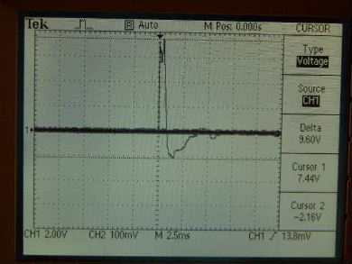
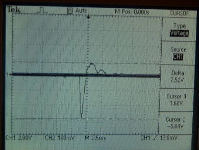
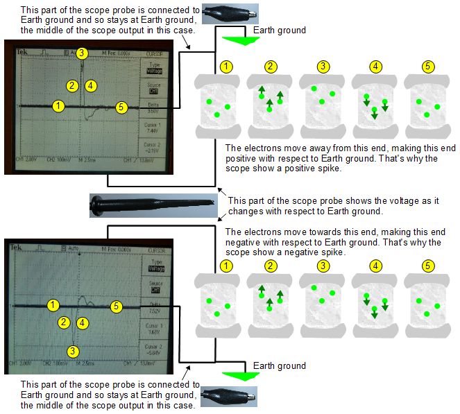
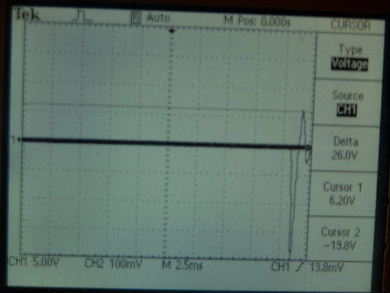
The following diagram is intended to explain why you get a positive spike if the oscilloscope probe is hooked up one way and a negative spike if it's hooked up the other way, as is demonstrated above. Notice in the diagram below that in both cases the electrons in the crystal move the same way during the tap. The difference in scope output is due to the way the spoke probe is connected to the crystal. In the positive spike case the electrons move toward the grounded probe tip and away from the ungrounded probe tip, leaving it positive with respect to ground. In the negative spike case they move away from the grounded probe tip and toward the ungrounded probe tip, leaving it negative with respect to ground.

The spike you see on the scope output represents what happens at the ungrounded probe tip. What happens at the grounded probe tip is nothing, because it's connected to Earth ground. On the scope output the grounded probe tip is represented by the horizontal line at 1 and 5 in the diagram and never moves vertically from that position.

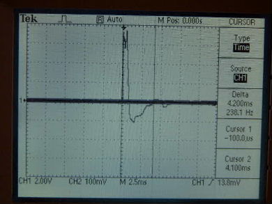
If neither of the probe tips were grounded then the scope output would be two lines that start out touching but then briefly move equally apart from each other, one in the positive direction and the other in the negative. Most benchtop oscilloscopes have one tip grounded. The crystal does have a specific end which will always be positive and the other negative when it is tapped and that's what you'd see.

Explanation of why the oscilloscope output shows positive and negative spikes depending on which way the probe is connected to the Rochelle salt piezoelectric crystal.
Diagram of what happens to the electrons in the crystal and on the oscilloscope output when the crystal is tapped. The top case has the scope probe tips connected to the crystal one way and the bottom case has the scope probe tips connected to opposite way.
Oscilloscope output showing results of a really hard tap on piezoelectric rochelle salt crystal.
Here is the result of a really hard tap... 26 volts.

Video - How to test a Rochelle salt crystal

One of the times I made some crystals I decided to make a video of my testing. Enjoy!

Other Piezoelectricity explorations

More topics

rimstar.org - Share your project on rimstar.org - About - Privacy policy - © 2020 Steven Dufresne
Contact: