This is still a work in progress. Making this thing in such a way that
it meets the specifications necessary to test the theory is very
difficult. For example, I spent a few weeks in April working on finding
a good enough way to
make a barium titanate dielectric.
Even then I may have to build a new one since I realized that the
air gap I left between the two output cylinders is too small and
will arc when the
voltage is applied.
At this point I am able to demonstrate that the output cylinders embedded
in the capacitor hold their charge, even when they are "shorted". This is
crucial since that charge has to be there while the voltage is being
fluctuated in order to create particles.
A demonstration that charging works
The following is a video demonstrating the charging and that the
charge stays even then a load is applied. Note that after making the
video I redid the test using a piece of copper (i.e. low resistance)
as the load and the output cylinders still held their charge.
The power supply used in the test in the above video was one with
three outputs: HV+, ground, HV-.
Click here for more details about this power supply.
The following is the sequence of steps demonstrated in the above video.
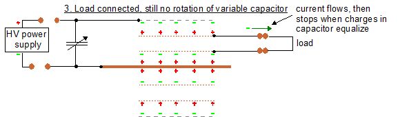
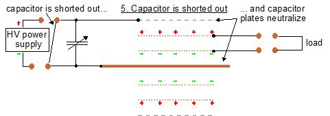
These are the last steps shown in the video. Their purpose was to
demonstrate that the copper mesh output cylinders really were charged.
This is done by first neutralizing the capacitor plates (the outer
aluminium perforated cylinder and the inner copper rod.) After step
5 below, there is no more capacitor charge to hold the charge on
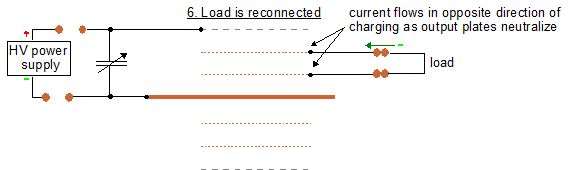
the output cylinders but their charge has nowhere to go. Then, in
step 6, a path is given. Notice that the current flows in the opposite
direction that it did during charging in step 3 above. This is shown
in the video on the scope when the polarities in step 6 are the opposite
of those in step 3.
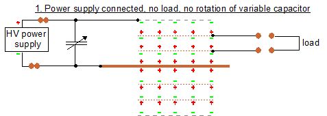
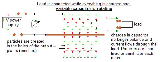
How it should work when finished (if it will actually work)
This is what everything should look like once the output cylinders
within the capacitor are charged and the variable capacitor rotating
and adding voltage fluctuations.
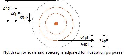
Construction
The capacitances.
 |
|
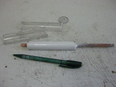
The Barium Titanate and epoxy dielectric straight
out of the mold.
 |
|
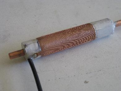
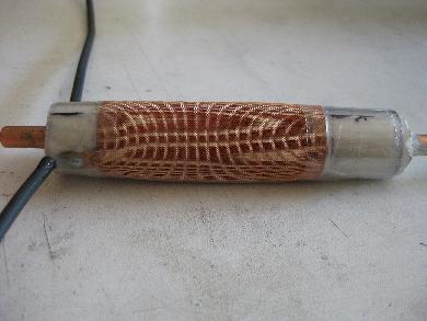
The first output cylinder is attached.
 |
|
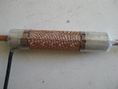
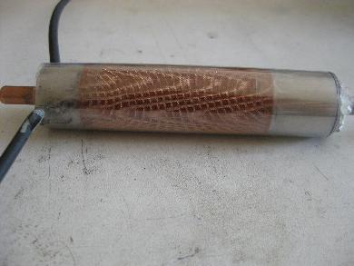
Two layers of acrylic sheet spacers are added,
including in the middle for where the second cylinder's
ends will meet. Notice that this will leave an air gap between the
cylinders.
 |
|
The second output cylinder is attached - view showing
the place where the ends meet.
 |
|
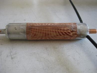
The second output cylinder again - showing the side
where the wire is attached.
 |
|
Two layers of acrylic are wrapped around - notice
the cylinder is completely covered.
 |
|
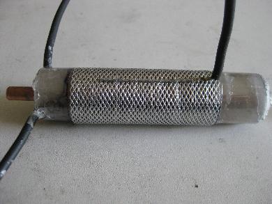
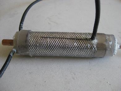
The perforated aluminium outer cylinder is added.
Notice the nylon fishing line wrapped around it holding the cylinder
in place and
holding the connecting wire firmly against the cylinder.
 |
|
Spacers are added to the end and epoxied in place.
This was important to inslute this outer cylinder from the two
copper mesh output cylinders inside. Without doing this, ions
would likely flow between them.
 |
|
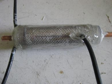
The whole finished thing with arcylic wrapped
around it. Notice all the epoxy added to the ends (and where
two ends of the acrylic overlap - not shown) and where the wire
would otherwise be exposed.
 |
|
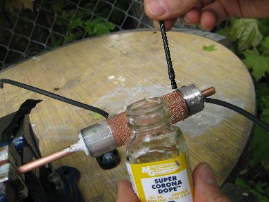
This shows an earlier version and shows how I
coat all edges with corona dope.
 |
|