Construction of Full Cylinder, Dual Dielectric e-field Thruster 1 - Epoxy dielectric part

Prev - Construction page 1, 2, 3, 4 - Next

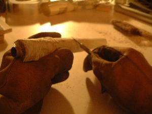
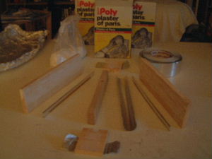
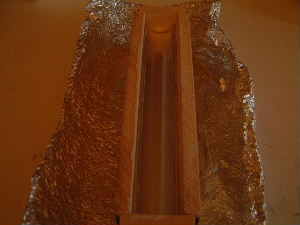
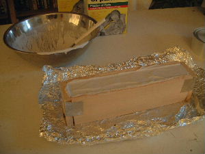
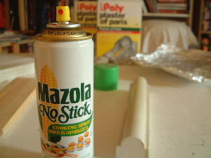
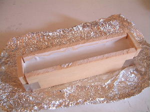
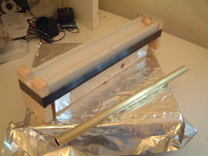
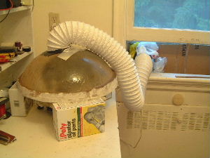
September 28, 2003 - Molds done and epoxy poured

I first cut the tubes to the correct lengths using some very useful cutting tools.
Pipe cutting tools for cutting cylinders.
The parts needed for the first plaster mold.
The parts needed for the plaster of paris mold.
The parts assembled -- ready for pouring the plaster.
Ready for pouring plaster of paris into the mold.
The plaster has been poured.
The plaster poured into the mold.
The resulting plaster mold. I call it the negative since it is the exact opposite of the final mold that I need. It will be used to make the positive.
The resulting negative made of plaster of paris.
I put a thin layer of oil on the negative so that I will be able to separate it from the positive. In my first attempt I didn't do this and was unable to separate them.
Putting a thin layer of oil/lubricant on the plaster negative
      so I can separate it later.
The negative is in place and the plaster has been poured.
The negative in place in the mold and the plaster of paris
      has been poured in to make the positive.
The end result. The negative is on the left and the positive is on the right.
The resulting negative and positive.
The positive is in place. Everything is now ready for pouring the epoxy. I'll pour a little in first, then put the brass tube in place, then pour the rest. Note the round slots cut in the endcaps for placing the ends of the brass tube in. These are very precisely aligned so that the brass tube will be centered in the positive.
The positive mold in place awaiting the pouring of the epoxy.
The epoxy has now been poured and the brass tube is in its correct position.
The epoxy poured into the mold and the brass cylinder
      in place.
It has gotten too cold to let the epoxy harden outside. So I've set up this ventalated fume hood. There is a fan in the window sucking the air out.
The fume hood in use while the epoxy hardens.

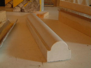
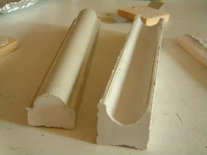
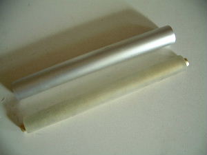
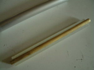
October 2, 2003 - Removed plaster from epoxy
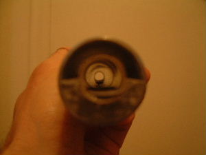
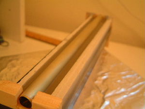
Scraping away the plaster from the epoxy.
Scrapin gaway the plaster of paris from the epoxy.
Bottom view of epoxy part.
Bottom view of the epoxy part for the electric field thruster
      capacitor.
Top view of epoxy part.
Top view of the epoxy part for the electric field thruster
      capacitor.
End view of epoxy in place (though not permanently). Note that it is not quite a half circle.
End view of the epoxy part for the electric field thruster
      capacitor.
Other end of epoxy in place. Note that it is even less of a half circle at this end.
Other end view of the epoxy part for the electric field thruster
      capacitor.
View showing how good a fit the epoxy is with the aluminum tube.
View of the epoxy part for the electric field thruster
      capacitor showing the fit with the aluminium cylinder.

Prev - Construction page 1, 2, 3, 4 - Next

rimstar.org
Contact:
Liked this? Share it with: