Prev -
Construction page 1,
2,
3,
4 -
Next
Objective was to find a method of making the rounded ends for the outer electrode
tube. The desired side profile as drawn by Zoltan Losonc is as follows:
Specifically it is the grey cutaway circle drawn just above where 'a' and
'b' are pointing to. The idea is to eliminate the sharp ending of the
outer electrode tube. 'a' and 'b' are pointing to where thick resin
will be poured in order to produce a smooth, well rounded meeting of the
end of the electrode and the circle (tube) represented by the grey circle.
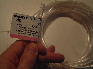
The vinyl tube used. This will be the small grey circle
in Zoltan's drawing above.
 |
|
Original Krazy Glue turned out to be perfect for holding
the two ends of the vinyl tube together. It is very hard to pull apart.
 |
|
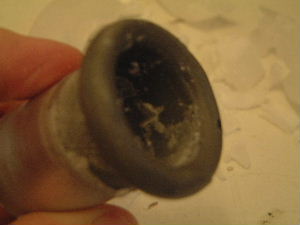
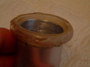
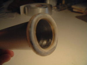
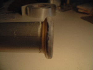
Inside view of the vinyl tube in place with resin already
hardened onto it. Note that since it's really a test and learning experience,
it's a little bit sloppy.
 |
|
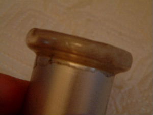
Side view of the vinyl tube in place.
 |
|
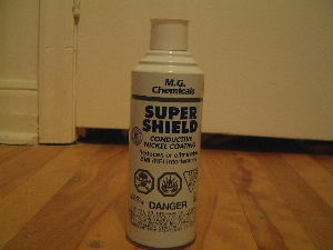
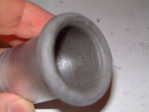
Inside view of the vinyl tube after painting with
the conductive nickel paint.
 |
|
Side view of the vinyl tube after painting.
 |
|
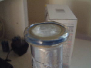
Following on the above October 12 tests, I put the test
piece in 80 degree C wax and let the wax harden. The idea was to test if the
air in the vinyl tube expanded strongly enough to deform the tube. It did not,
as the picture below shows.
Having past the tests, I next had to attach the vinyl tubes to the real
outer electrode tube.
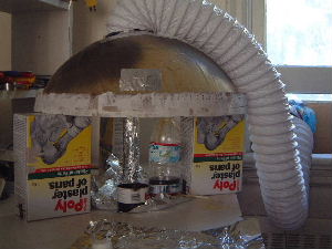
The "fume hood" for letting the resin harden inside.
 |
|
A wax plug was put in the middle so that the resin
would not drip much into the outer tube. Also, the wax plug is easy to
remove. The resin has already been poured. Notice that the vinyl tube
has blue wires inside it. This is to
reduce the amount of air in the tube. The wax test mentioned above proved
this to be unnecessary but I didn't complete that test until the wires were
already in place.
 |
|
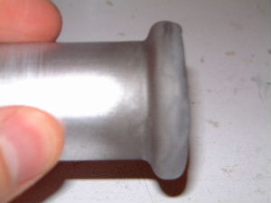
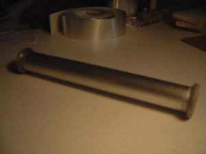
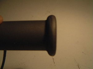
The end result after sanding.
 |
|
Another view of the end result.
 |
|
The two end tubes attached.
 |
|
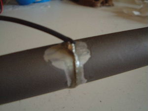
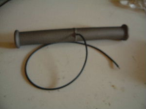
To attach the wire, at Zoltan's suggetion I removed the insulation from enough
wire so that I could wrap the wire around the tube, twist it tightly against
the tube and then solder the twist. Naturally I first sanded the insulation
off of the tube before putting the wire on. I then put resin on it so that
the paraffin wax would not get under it and potentially make it lose contact
with the tube.
 |
|
The outer electrode with the wire.
 |
|
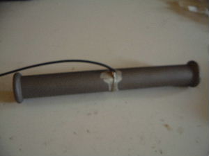
The outer electrode fully painted with the conductive
nickel paint. Notice that the entire outer electrode has been painted. It
turned out that the outside of the aluminum tube (but not the inside) was
coated with something nonconductive. Rather than make a mess sanding it off,
I decided to simply paint over it. This wasn't really necessary since the
outside will be ground and the field will be very weak on the outside but
I did it anyway.
 |
|
View of one of the ends.
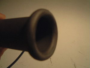 |
|
Another view.
 |
|
Prev -
Construction page 1,
2,
3,
4 -
Next