Prev -
Construction page 1,
2,
3,
4 -
Next
I glued the epoxy piece to the inside of the outer electrode. The glue
I used was the very same epoxy that the epoxy piece is made of. Since
the epoxy piece was already a tight fit with only the possibility of some air gaps
I decided not to paint the entire bottom with epoxy before putting it in.
This might have caused all sorts of new air gaps. Instead I spread very
thin layers onto the epoxy piece along the top 2mm (roughly) of the
outer edge of the epoxy piece. I then slid the epoxy piece into the
outer tube while holding it firmly against the tube so that excess
epoxy would scrape off. I then cleaned off the excess.
Once this was done, I then painted more epoxy
at the openning of the outer tube where the tube met the epoxy piece.
The overall idea was both to hold the epoxy piece firmly to the tube
and to prevent paraffin wax from later getting between the epoxy piece
and the tube. Once it is dry I'll paint more nickel paint over any parts
of the ends of the outer tube that have epoxy on them but shouldn't.
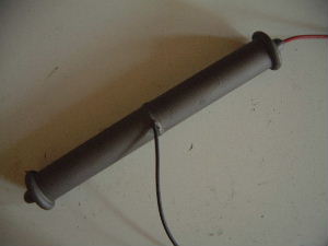
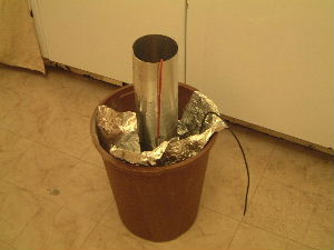
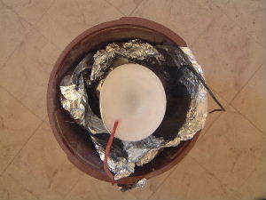
The final assembly sitting loosely on the vice.
The cup of epoxy and the paintbrush used are to the left of the vice.
 |
|
|
|
|
|
|
|
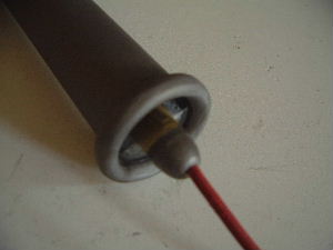
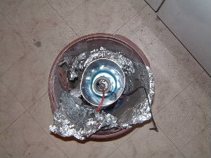
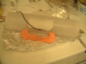
I should have placed the epoxy in the thruster such that
the black wire would be at 90 degrees to the side of the thruster instead of
on top of the thruster (as in the picture directly above). This makes it
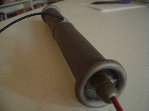
easier to do measurements using a scale. So I used resin to redirect the
wire as shown.
 |
|
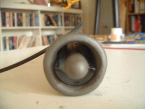
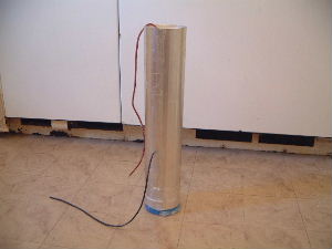
The end result of this one was no good as it left air cavities. This was
discovered when the thruster arced internally at 8kV.
The thruster was held suspended in the mold using
4 pieces of fishing line.
 |
|
|
|
|
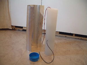
Note the shrinkage of the wax in the center. These
were topped up 4 times until no more shrinkage was happening.
 |
|
|
|
|
To be able to sit the thruster on the scale, it had to
have a flat bottom. Wax was added to make flat bottoms on the top and on the
bottom.
 |
|
|
Prev -
Construction page 1,
2,
3,
4 -
Next