For my testatika and
my vacuum energy tapping
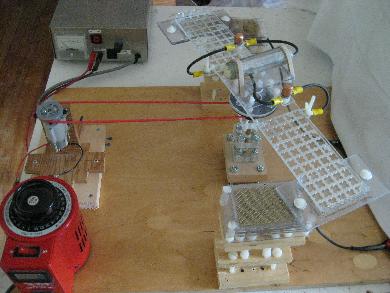
experiments I needed a rotating arm or disk with the following features:
- adjustablity to get rid of wobble
- able to distribute high voltage to segments and parts mounted
to the arm or disk
- very adjustable way of having parts that faced the arm or
disk but that did not rotate
Basically, since I can't make precision parts I had to make
something with the correct adjustablity to make up for the lack
of precision. This is what I came up with.
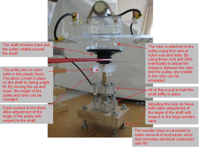
Adjusting the rotor
The pulley belt
The pulley belt is a long length of heatshrink tube normally
used for adding electrical insulation to wires. The following
video shows how it was made.
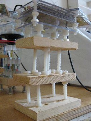
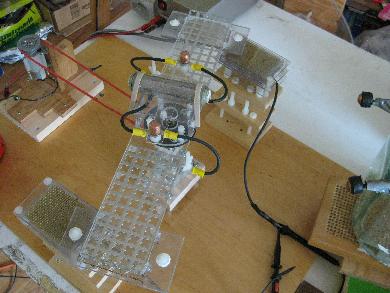
Towers for parts facing the rotor
A problem I've had in the past was how to have infinite adjustability
in the position of objects facing the rotor. This horizontal layout
was chosen to solve that problem. The towers shown below support
parts facing the rotor. Using all the various nuts and bolts, the tilt
and height can be adjusted and by sliding the towers around horizontally
on the wooden base, their location with respect to each other and
the parts on the rotor can easily be changed.
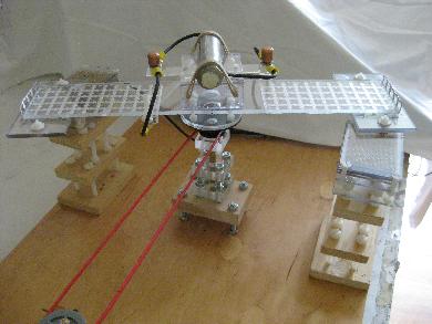
A sample rotor
Using the above basic structure, pretty much any rotor can be
used. I even left room for one that is a complete disk.
As an example, the following subsections contain details
of the first one I made for this structure, illustrating what
I hope are some useful ideas for adjustablity and charging.
The original purpose for this rotor was to search for the
principle behind
testatika principle experiment though I've used it for
other things as well.
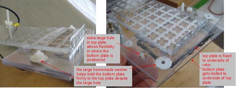
Adjustable end plates
A brass mesh glued under the bottom plate.
 |
|
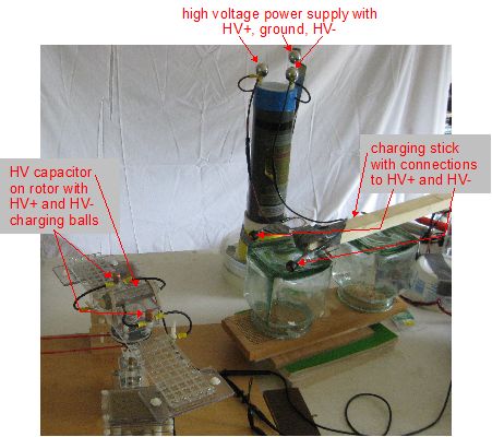
How it's charged
As shown below, the rotor carries its own high voltage in the form
of a homemade high voltage capacitor. A charging stick was made
that has two balls on it, each of which is wired to
my positive/negative high
voltage power supply.
Before starting rotation, the the two balls on the charging stick in
contact with two smooth surfaced balls mounted on either side of
the capacitor, each of which is wired to one plate of the capacitor.
The charging stick's balls in contact
with the balls on the rotor during charging.
 |
|
Charging complete. The charging stick is moved away.
 |
|
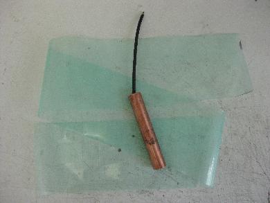
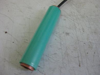
The homemade HV capacitor
The HV capacitor consists of an inner copper cylinder cut from a half
inch hollow pipe, around which is a sheet of polyethylene wrapped around
a few times, followed by a thin sheet of copper. All of this is wrapped
with acrylic sheets and further encased in epoxy and plastic endcaps.
From the web, the breakdown voltage of polyethylene is 25kV/mm so I
wrapped enough polyethylene to make up just over 1mm thick. The
capacitance is 39pF. Click on the photos below for larger versions.
The capacitor is held onto the rotor with rubber bands and so that it can
easily be replaced with another.
Selecting the polarities for the rotor
I wanted to be able to have the following options for the polarities
of the parts on the two ends of the rotor arm:
- both HV positive,
- both HV negative, or
- one HV positive and the other HV negative.
The following photos illustrate how that's done. The first two are
actually redundant since the cylinders of the capacitor can be
charged either way: outer cylinder HV+ and inner cylinder HV-, or
outer cylinder HV- and inner cylinder HV+.