I had a UHF oscillator circuit designed to output a range of frequencies from 200MHz to 380MHz but no way to test it. So I made up a lecher line so that I could measure the frequencies I could produce. I learned how to do this from this page.
A lecher line is a transmission line on which you can put Very High Frequency (VHF, 30MHz to 300MHz) and Ultra High Frequency (UHF, 300MHz to 3GHz) electromagnetic waves. It's made up of two parallel wires or rods which are connected at one end. The wires are spaced no more than a foot apart. The length is selected based on what frequency you wish to put on the line.
|
Determining the length of lecher line needed
In my case I was putting frequencies in the range of 200MHz to 380MHz, or 200 million cyles per second to 380 million cycles per second. A single cycle is one wavelength (the length of a single wave) so we could also say my frequencies were 200 million wavelengths per second to 380 million wavelengths per second. Since these are electromagnetic waves they travel at the speed of light, which is roughly 300,000,000 meters per second. We want the lecher line to be at least the length of one wave so we want to find out the wavelength. Given a frequency and the speed of light, it's simple to do that. The formula for a wavelength is: wavelength = speed of light / frequency.
Example: wavelength of a 200MHz wave = 300,000,000 / 200,000,000 = 1.5 meters
Example: wavelength of a 380MHz wave = 300,000,000 / 380,000,000 = 0.79 meters
So my lecher line needed to be at least 0.79 meters and at most 1.5 meters. Actually, a lecher line that is half the wavelength will work too if you're short of wire. Mine was only 1.12 meters.
Setting up the lecher line test
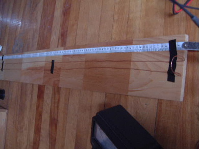
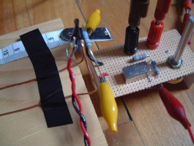
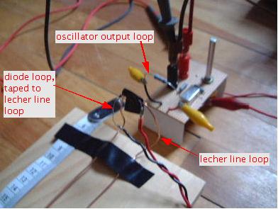
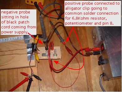
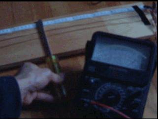
From the photo above you can see that my lecher line was really made up of a single wire that had a loop at one end. The loop serves two purposes. The obvious purpose is so that the wire can be bent to form two parallel lines. The other purpose is because we need a way to put our frequencies on it, the output of my oscillator. I did this by forming a similar loop at the output of my oscillator and putting the two loops close together but not touching. This way the frequency in the oscillator loop was induced onto the lecher line. As a side note, notice in the photos below that I attached a 6.8Kowm resistor to the two output wires from the oscillator in order to make the oscillator loop. This was because I didn't want to use a dead short, so I picked a resistor at random.
|
|
|
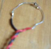
In these photos you can see the two loops but also something else. That something else is a diode loop that is connected to the probes of an analog meter via some wires (the twisted red and black wires in the photo.) The diode loop is taped to, but electrically isolated from, the lecher line's loop so that the lecher line loop will induce current flow in the diode. Since the diode will alow current to flow in one direction only, it will register on the analog meter as a DC voltage.
Not just any old diode will do. It must be a diode that will work in the frequency range being tested, in this case a UHF (Ulta High Frequency) range. I hunted around and found an NTE583 silicon "Shottky Switching for High Level UHF/VHF Detection and Pulse Application" diode (NTE catalogue description) in a local electronics store (Gervais Electronics for anyone in the Ottawa area.)
Notice that I taped a measuring tape beside the lecher line. That's to make it easy to measure distance, as you'll see below. Notice that the end of the measuring tape extends past the end of the line. That's to take into account the height of loop. The measuring tape is showing centimeters (cm) since the calculations are using meters (1 meter = 100 centimeters.)
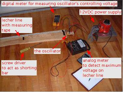
As the photos below show, I use a digital multimeter to measure the controlling voltage that's feeding the oscillator in order to select the frequency.
|
|
How the lecher line test is done
The test is done by moving a shorting bar, in this case a screw driver since we don't want to touch the metal, along the line. The metal shaft of the screw driver should touch both wires as you move it, shorting them, hence the term "shorting bar". The idea is that when the screw driver is at the position on the wire that is a half wavelength or a full wavelength from the loop end then the voltage on the analog meter will suddenly jump to a maximum value. The following video demonstrates this.
|
You may need QuickTime to view it. If you don't have QuickTime you can download it here.
As said above, the position of the screw driver along the line when the voltage on the meter is at a maximum is the position of the half wavelength or wavelength of the frequency currently being induced onto the line from the oscillator. So now that we know the wavelength we calculate the frequency by doing the opposite calculation that we did above: frequency = speed of light / wavelength
Example: frequency = 300,000,000 / 0.775 = 387,096,774 (or 387MHz)
If your measurement was taken at half the wavelength then simply double it. For example, if the distance along the measuring tape when you saw maximum voltage was 37.5 cm, which is 0.375 meters, and you knew this was only a half wavelength, then double it for 0.775 meters and do the above calculation.
Lecher line test results
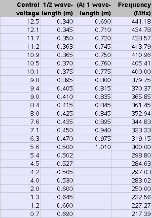
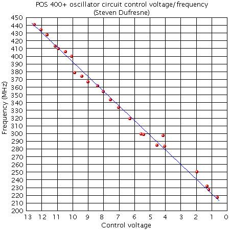
Using the above method I was delighted to see that by adjusting the potentiometer on the oscilllator I could vary the frequency throughout the documented range, and even above it. The following table and chart show these results. Just as the data sheet for the Mini-Circuits POS400+ states, as the control voltage gets nearer the bottom end, the frequency varies more per volt meaning that a small adjustment on the potentiometer made for a big change of control voltage and hence the frequency.
The smallest DC scale on my analog meter was the 1 volt scale. This was a problem in that for a control voltage like 9.8 volts, when hunting for the 1 wavelength distance, the meter needle would stay below 0.2 volts, the bottom of the meter range. Also, the maximum deflection was a small fraction of that so the needle would barely move at all, making it difficult to tell if/when it was at maximum. The lower the control voltage (longer the wavelength) the less the maximum deflection to the point where it barely moved above normal. That's why in the table there are no 1 wavelength values for the lower control voltages. For that reason, the frequency below is calculated using 2 times the 1/2 wavelength. The 1 wavelength data points are ignored in the frequency calculation.
For 1/2 wavelength the maximum deflection was larger for a longer range than for 1 wavelength but below a control voltage of around 4 volts, it also was small enough to become highly error prone. A meter with a lower voltage scale would have helped.
|
|