This is a UHF oscillator circuit I designed to make use of the
Mini-Circuits
POS-400+ voltage controlled oscillator chip. By giving it a voltage from
0 to 12V on pin 8 it gives out a sine wave ranging from 200MHz to 380MHz on
pin 2, though my testing with a lecher line gave a range of 200MHz to 440MHz.
The purpose was to use it as a frequency source for the
testatika Linden experiment
under the assumption that the experiment's long wire is a lecher line
that is 1 metre long, the wavelength corresponding to 300MHz which in turn
corresponds to the speed of light (approximately 300,000,000 metres/second.)
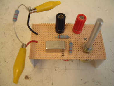
The chip in place with a homemade circuit and a resistor for
the load.
 |
|
Construction of the UHF oscillator circuit
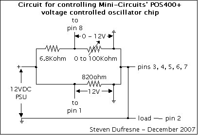
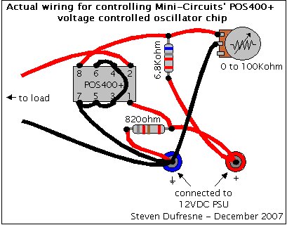
Basically I needed two 12VDC sources, one fixed at 12V for feeding pin 1 and
one that could vary between 0 and 12V for feeding pin 8, the latter for selecting
the frequency (from 200MHz to 380MHz.) Unfortunately I didn't have two 12VDC sources
where one leg of each was connected to ground. I had a power supply that I'd built where
that was the case but everything else I had had both legs floating as far as I
could tell. So somehow I had to come up with a circuit that would allow my
one power supply to provide both fixed 12VDC and variable 12VDC. I came up with
the following circuit.
It uses the fact that a single 12VDC source can be made into two separate ones
by use of two parallel lines (the top and bottom horizontal lines connected to the
positive leg in the above),
the voltage supplied to both being 12V but the
current being divided, which I didn't care about since I had enough current.
For the variable line I used the fact that voltage drops across a resistor,
the bigger the resistance the bigger the voltage drop. Since I needed various
voltages I used a potentiometer for the resistor (a potentiometer is a variable
resistor.) That way I could choose the size of the voltage drop, and hence the
frequency, by simply turning the potentiometer knob.
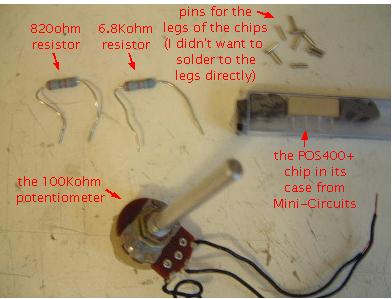
I tried a few different larger potentiometers (5Kohm and 50Kohm) but the
voltage drop range they gave was too narrow. The 100Kohm worked best.
I put a 6.8Kohm resistor in series with the potentiometer for the case where
the potentiometer was turned all the way down to 0ohms. I'd need some resistance
remaining on the top 12V line so I chose a 6.8Kohm resistor. I wanted it big
so that it would be big in comparison to the bottom line's resistance, 820ohms.
The specifications for the POS400+ chip requested that maximum current be 20mA.
At first I had a 100ohm resistor instead of the 820ohm but the when the potentiometer
was turn up all the way, the current through the 100ohm was too large so I
tried 820ohms and it worked fine to limit the current to something close to but
not above 20mA.
Bottom view.
 |
|
|
The parts.
 |
|
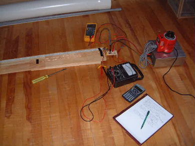
Testing the UHF oscillator circuit
Testing my circuit meant seeing if adjusting the potentiometer caused
the output to range from 200MHz to 380MHz. Unfortunately my oscilloscope
is limited to 100MHz. So I used a lecher line to test it.
Click here to see the tests using a lecher
line. The oscillator circuit is being powered by my
homemade 24V power supply.
Using a lecher line to test the UHF oscillator circuit.
 |
|