My HVG10 high voltage power supply puts out
from 24kV to 75kV positive with respect to ground whereas I needed
something that put out just a few thousand volts negative with
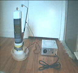
respect to ground. Luckily, the tall grey cylinder my the HVG10 pictured
below contains a single circuit board immersed in mineral oil that is all
that needed to be replaced in order to do this.
My HVG10 power supply.
 |
|
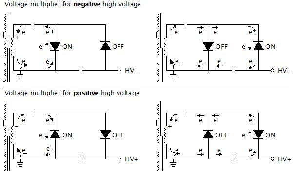
Most multiplier schematics you see are for positive output. To get
negative output you simply reverse the direcition of the diodes.
The squigly lines on the left in the diagram above represent an AC source,
in this case a flyback transformer, which is part of the the input to the
circuit board and everything to the right is the circuit
board contents. A full schematic of an example of the input
(non-voltage multiplier) side, of things can be found on
this page about my 30kV power supply.
Construction details
I ordered the high voltage diodes and capacitors both from
Information Unlimited,
the same place that I bought the HVG10 power supply from many years ago.
The diodes are their part number VG12 (12,000V, 10mA diodes, .625 x .13"
rectangular epoxy coated, unmarked, 100 nanosecond fast recovery devices for
use with high frequency switching circuits, avalanche diodes.)
The capacitors are their part number .001m/20KV (0.001microfarad, 20kV ceramic
disk capacitors.) Note that I didn't do any special calculations in selecting either of
these parts. I simply looked for inexpensive high voltage, high frequency diodes and
high voltage, non-electrolytic capacitors.
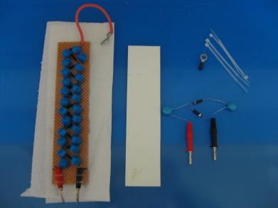
The 24kV to 75kV positive output board that came with the
power supply is on the left. On the right are the parts for my few thousand volts
negative version.
 |
|
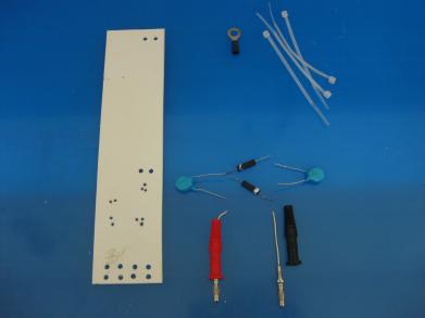
I just used a sheet of 1/8" thick white plastic for the board.
Any insulating material will do. These are the parts after drilling holes in the
plastic board.
 |
|
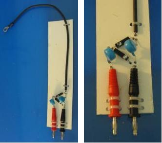
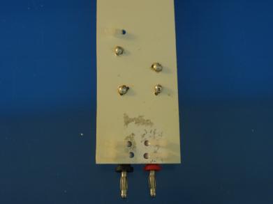
The completed voltage multiplier circuit.
 |
|
Notice that the soldering was done with big rounded blobs
of solder. Since this is high voltage, you want to avoid any sharp metal edges.
 |
|
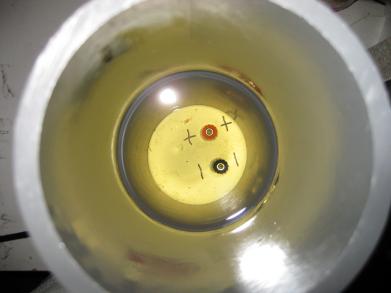
View looking down into the grey PVC tube at the banana connectors
at the bottom. The other side of these connectors goes to the flyback transformer
and to the ground connection.
 |
|
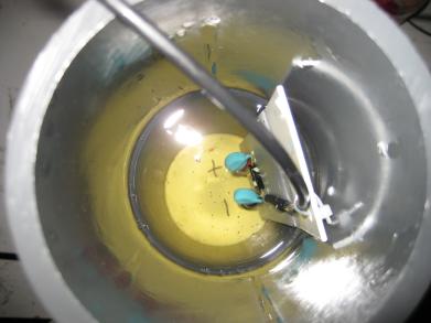
The circuit connected in place. Note that the part of the
circuit board with the actual components on it is immersed in mineral oil to
prevent arcing between the components.
 |
|
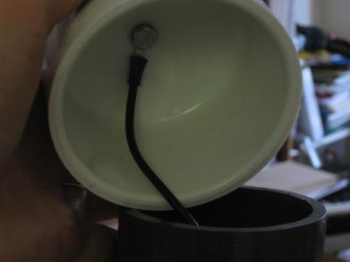
The negative output wire is connected to the head of a bolt
in the underside of the tube's cap.
 |
|
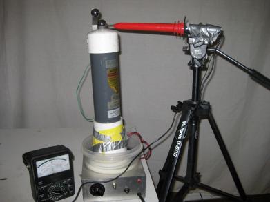
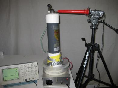
Testing the voltage multiplier
In the photos below I'm using my
40kV Fluke high voltage probe to measure voltage.
Around -4.6kV on the analog multimeter. For the needle to
move to the right the leads had to be connected to the meter backwards.
 |
|
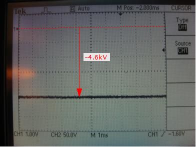
Around -4.6kV on the oscilloscope.
 |
|
-4.6kV. This is just after turning up the dial on the power
supply to where it first starts working.
 |
|
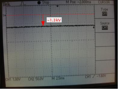
-1.3kV. This is gotten by next turning the dial back down slowly.
If I continue to turn the dial any lower then the voltage drops to zero. So -1.3kV
is around the lowest I can get with this board and power supply.
 |
|
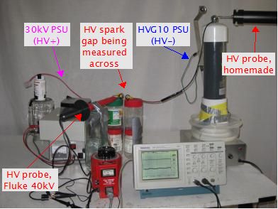
The whole reason I made this negative high voltage board was I needed
to be able to charge a capacitor with HV+ on one plate and HV- on
the other place instead of HV+ and ground respectively. So I
used my 30kV power supply for the
positive and this new, modified HVG10 power supply
for the negative. I used my store bought 40kV Fluke
HV probe connected to the oscilloscope's channel 1 to measure the positive
and my homemade
> 40kV HV probe connected
to channel 2 to measure the negative, both relative to ground.
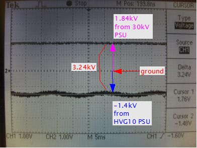
As you can see from the following photos, the combination worked.
The slight AC ripple on the lower line from the HVG10 PSU is noise
picked up by the homemade probe from the 60Hz household AC lines.