I needed a high voltage probe for measuring the voltage from my
HVG10 high voltage power supply. It puts out DC voltage
using a Cockroft Walton voltage multiplier (so DC with ripple).
So my probe is intended to work with DC only. To do this I followed the
very helpful instructions on the
Basics of High Voltage Probe Design page. I also drew inspiration
from the amazing probe shown on the
High Voltage Probe (> 50kV) page. Special thanks to Zoltan Losonc
for all his valuable help. The calculations I made
were for 50kV and 150kV. I say it is a > 40kV probe because the
probes you commonly find in electronic shops usually top out at 40kV.
In the end, safety measures we added which will prevent it from going
over 250kV. How good it is up to 250kV is unknown.
The divider network for my probe consists of 25 resistors of
200M ohms +/- 1% each
from Caddock. The part
number is MX440-200M 1% and they were $9.56 US each. My DMM
has an input impedance of 10M ohm so I use a 10M owm resistor for
measuring across. This also provides an alternate path for arcing
instead of my DMM. This combination gives me a dividing factor of
1000. So 50kV would read as 50V on my DMM. In hindsight I should have
bought higher ohm resistors so that my probe could be shorter.
2 corona gaps were put in place at 2 different points along the length
of the probe. My DMM has a maximum voltage rating of 1000V and I don't
want to exceed it. However, before 1000V would be reached at the DMM
the resistors would long since have broken down. To prevent this a
maximum output voltage of 250V will be allowed. So the corona gaps are
designed to create an ion path (corona) when 250V would be reached on the DMM.
The calculations for where to position the gaps and the method for
how to determine the gap size were worked out by Zoltan Losonc and
can be found
here.
Schematic for the probe.
 |
|
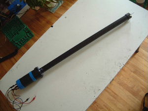
The final probe. From the end of the connectors
to the tip of the probe it is 1.27 meters (50.25 inches).
 |
|
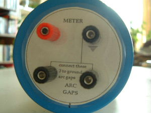
The connectors.
 |
|
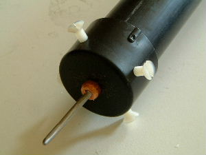
The probe tip.
 |
|
Construction
-
July 12, 2003 - Only up to 46kV
-
July 13, 2003 - Maxed out on variac without arcing (62kV)
-
July 17, 2003 - Solved the battery measurement problem
-
July 18, 2003 - Testing power line AC
-
July 20, 2003 - First high voltage measurements with oscilloscope
-
July 26, 2003 - Soldered resistor chain into final form
-
August 4, 2003 - Corona gap progress
-
August 11, 2003 - Corona gaps finished
-
August 11, 2003 - Stand-offs attached
-
August 23, 2003 - Waxing the connections
-
August 24, 2003 - PVC tube construction and chain insertion
-
August 24, 2003 - Testing


