Solar panel of transistor solar cells powering a calculator
After having experimented with a single solar cell made from a 2N3055 power transistor, I decided to try making a solar panel from multiple of them to power a calculator.
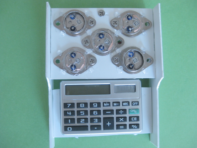
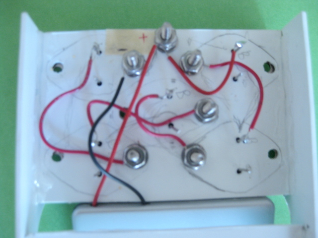
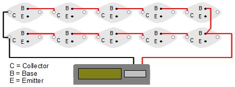
Here is the circuit diagram. They are wired in series to make the voltages add up. The calculator needs 1.5 volts.

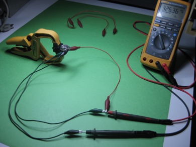
Notice that I didn't use the transistor's emitter pin, just the base pin and the collector, which is the case of the transistor. I did this because when I measured the power output for all possible wiring combinations for a single solar cell, using the base as the positive connection and the collector as the negative gave the best results as the following table shows.
|
Note that the above tests were done with two cool white compact fluorescent lightbulbs and not sunlight. This is fine since this calculator would be for indoor use.
Testing the transistor solar cell solar panel powered calculator
I first tested in sunlight (see photo on left below.) The sun was behind thin clouds and the light was coming through a flyscreen and two panes of window glass. It worked just fine.
Then I tested indoors with a yellowish 27 watt compact fluorescent lightbulb (see photo on right below.) I had to have the calculator 1 foot or less from the light to get enough power.
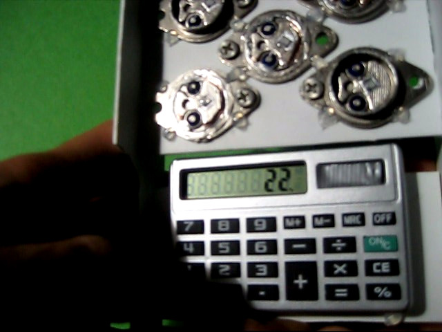
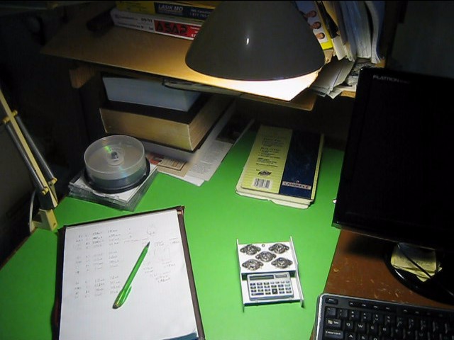
Since I did have to have the calculator relatively close to the indoor light to power it, I figure a solution would be to add a second set of five series transistors in parallel with the first set. I'm getting enough voltage so adding more in series wouldn't help but adding another set in parallel doubles the current. Unfortunately I ran out of transistors so I couldn't do it.
Video - Making the transistor solar panel
Here's a video of me making of the solar panel and showing it being tested.
Making a boxed, weatherproof transistor solar panel
You can make a box of some sort with a clear glass or plastic front and put the transistors in it for weatherproofing. That way you'll have a portable, outdoor solar panel. However, the transistors might get heated up from the sun and the hotter they get, the less efficient they'll be.
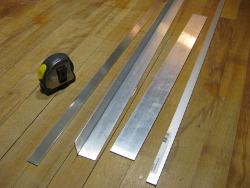
So you may want need to mount them on a heat sink, which is typically a piece of thick metal that conducts the heat away, often aluminum since it's such a great heat conductor. Once source of aluminum is places like Home Depot or Lowes and somes in the form of aluminum bars or angle pieces. This aluminum can be cut with a hack saw or a chop saw.
But there's a problem. If you mount them all to the same piece of metal then that will electrically connect all their collectors together; the collectors are the case. At this point you have two choices. Either:
- mount each transistor to it's own heat sink, or
- mount them all to one heat sink by using heat sink mounting kits.
Heat sink mounting kits allow the heat to conduct to the heat sink while preventing electrical contact between the transistor case/collector and the heat sink.
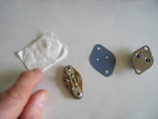
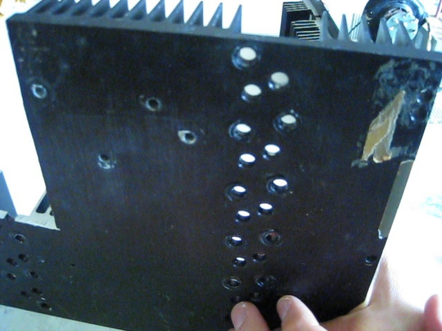

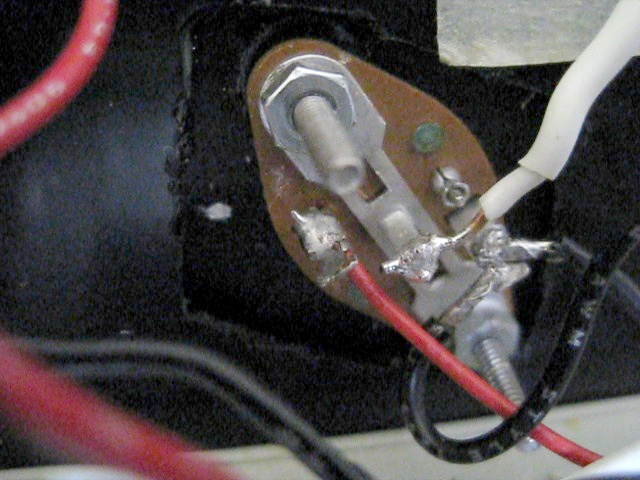
And if you go the mounting transistors to a heat sink using a mounting kit then the following video shows you step-by-step how to do it.
