How to make a solar cell (DIY/homemade solar cell) using a 2N3055 power transistor
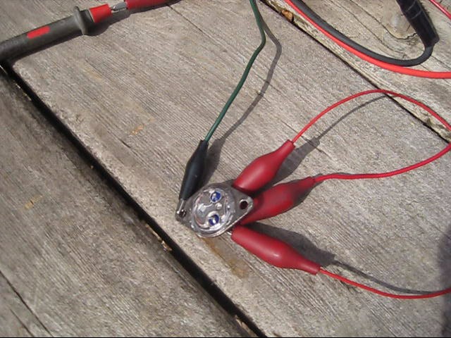
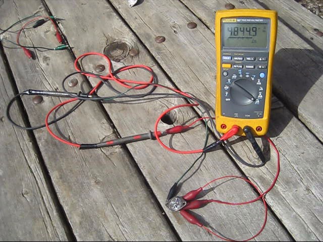
To easily make a homemade/DIY solar cell, get a power transistor like the 2N3055 and carefully cut open the case. That exposes the semiconductor material inside to light. Hook up some wires and you're done! Doing this I managed to get around 500 millivolts and 5.5 milliamps which is 2.7 milliwatts. To power a 15 watt compact fluorescent lightbulb I'd need at least 5555 of them. However, just 5 of them in series will power a small 1.5 volt calculator in good indoor lighting conditions.
Be sure to also check out the solar panel I made using multiple of these transistor solar cells for powering a calculator as well as this more powerful one enclosed in a box.
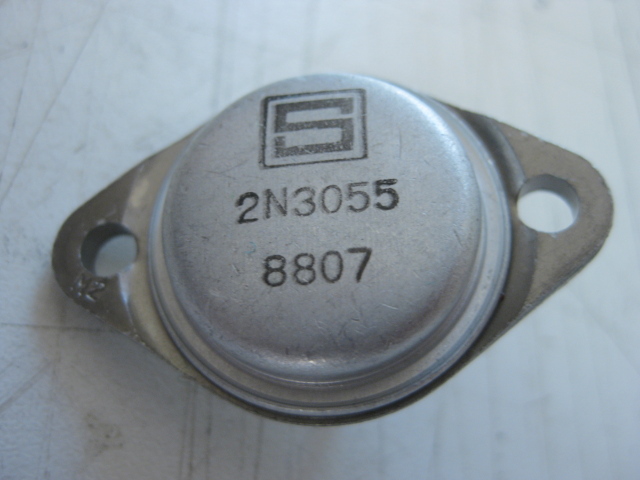
In the photo on the left below is the transistor.
Use a hacksaw to cut off the front of the metal case as in the photo on the right. There are thin delicate wires inside so when you cut, do many short cuts all around the case being careful to not let the blade go deeply inside the case. Don't do just one cut all the way through.

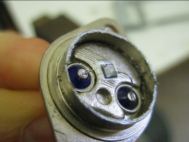
In the photo on the left, below the case has been cut all the way to the backing and the thin, delicate wires are completely unprotected. In the photo on the right only the front part of the case has been cut off, leaving a protective, cylindrical wall around the insides, giving some protection for the wires.
IMPORTANT: Almost every time that mine was not working, or stopped working, is because the middle of one of those delicate wires had been pushed down somehow and was touching something, creating a short circuit. You may need a magnifying glass to see it. If that happens, very, very, gently lift the middle of the wire back up so it forms an arc with the two ends still connected somewhere, as in the photos below. I use the tip of an x-acto knife for this but any narrow enough tool that can get under the wire will do. Be very, very careful not to disconnect either end of the wire from where it's connected. I don't know if you'd be able to reconnect it again if you do.
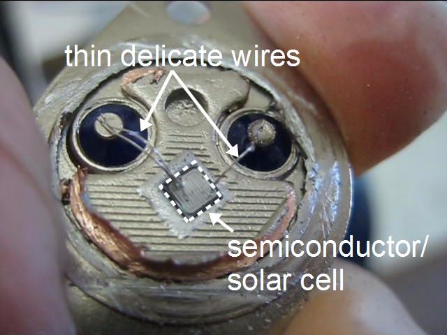
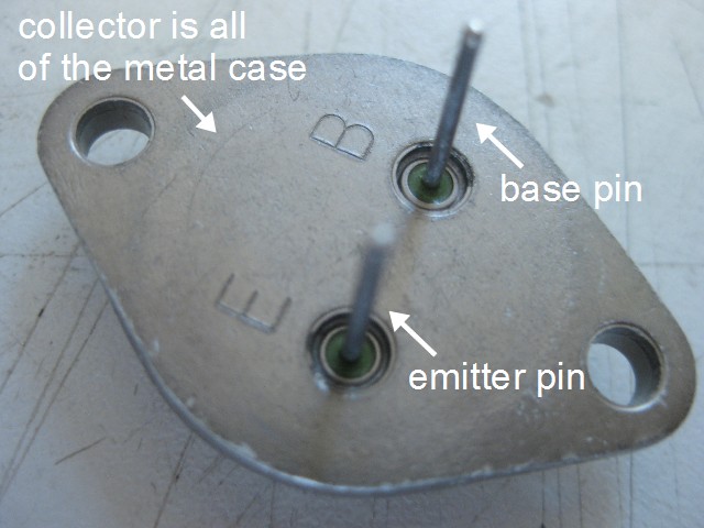
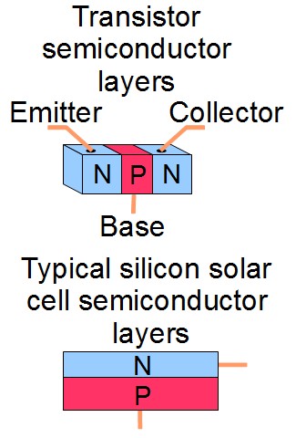
As shown in the photo and illustration, there are three points to make electrical contact with in a transistor unlike with a typical solar cell.
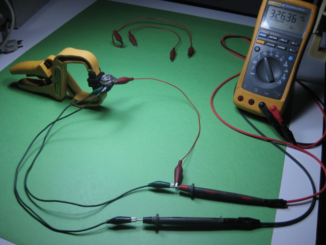
To know how to connect to the transistor to get the best output I set up a testing station where the transistor would be fixed firmly in place while I tried all the possible ways of connecting to it and measured the output for each way. The results are on the right, below. This was done indoors to get constant lighting conditions. Two cool white compact fluorescent lightbulbs were used. This means that the values are low and may scale differently in sunlight since sunlight has a different range of frequencies.
| Test | Voltage | Current | Power |
|---|---|---|---|
| Base+, Emitter- | 370mV | 94uA | 35uW |
| Base & Emitter+, Collector- | 325mV | 215uA | 70uW |
| Collector-, Base+ | 340mV | 265uA | 90uW |
| Collector+, Emitter- | 28mV | 65uA | 1uW |
As you can see from the table above, using the Collector as negative (i.e. connecting to the metal case) and the Base as positive (i.e. connecting to the Base pin) while ignoring the Emitter gave the best results.
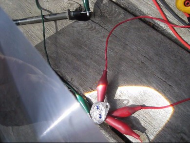
And lastly, for fun, I played around with focusing light on the solar cell using a small Fresnel lens to see the difference it made. I got around 520 millivolts and over 5.5 milliamps (measured on the microamps scale, the milliamps scale on my meter is broken.)
Video all about the 2N3055 transistor solar cell
Here's a video I made about my experimenting with this 2N3055 transistor solar cell.


