555 timer chip musical instrument
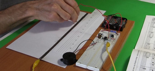
I made this very simple music instrument/keyboard for playing music using a 555 timer chip circuit, a piece of paper and a pencil. To see it in action watch the how-to-make video below.
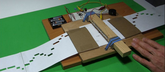
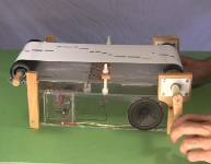
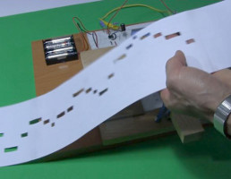
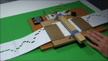
And then I made the much fancier automatic music player in the photo below by making a playing head and a way to feed in a long sheet of paper with the musical notes represented as holes in the paper. To see it in action watch the how-to-make video below.
How they work
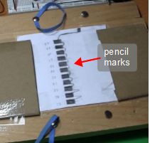
Below are drawn the circuits used for the above music devices. The "paper and graphite resistor" refers to a sheet of paper with thick pencil marks drawn on it. This pencil marks acts as variable resistors. In the circuit below you can see it's wired in series with the 6.8 kilo ohm resistor. By moving the end of the red wire across the marks, the 555 chip sends different frequencies to the speaker.
The two circuits differ in the shape of the pencil marks for the paper and graphite resistor and in the capacitance of one of the capacitors. In the circuit on the left the capacitor is a 0.1 microfarad one and on the right it's a 2.3 nanofarad one. Using the smaller capacitor allows for thinner lines with higher resistance to be drawn between each rectangular mark for the graphite resistor. The higher resistance makes it easier to make marks that represent different musical notes.
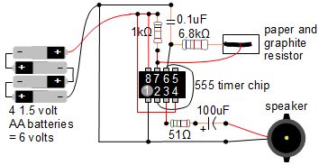
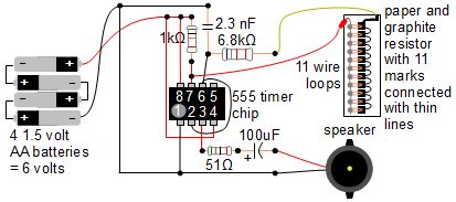
But more importantly, the two circuits differ in how contact is made with the pencil marks/graphite resistor.
In the first circuit the contact is made by touching it anywhere with a wire. You can see this in the circuit diagram on the left above and in the photo below.
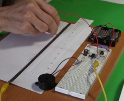
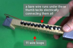
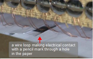
In the second circuit contact is made as follows and as shown in the photos below. Each rectangular pencil mark represents a different musical note. Contact is made with the marks using one of 11 wire loops. To contact only one mark at a time, holes have been made in a long strip of paper. As the paper is pulled between the wire loops and the pencil marks, one hole in the paper will allow one loop to contact a mark. When it does, electrical contact is made and the musical note represented by that mark is played. Pulling the paper along, plays a song, in this case the first part of Greensleeves.
Video of how to make the 555 timer circuit and simple music instrument/keyboard
Here's my step-by-step instructional video for how to make the circuit on a breadboard along with a very simple keyboard. Also included is a demonstration of it in use. For details on how to calculate the right resistances for the frequencies to get the right musical notes, see the other video below for the music player.
Video of how to make the 555 timer automatic music player
This video shows how the automatic music player is made. For step-by-step instruction for the 555 timer circuit though, see the video above for the simple music instrument. The video below goes over how the playing head is made and goes into much more detail on how to select the proper resistance for getting the right frequencies for the musical notes. It also shows a demonstration of it in use and as a bonus, shows how to make a maze solver using the same 555 timer circuit.
Video of how to make the strips of paper with the holes
This video gives the bare essentials you need to know to read sheet music and then how to make the long strips of paper with holes in them representing musical notes so that you can make your own.
Spreadsheets for calculating resistances
For the simple music instrument which used just a thick pencil line as the keyboard, no calculations were done to work out the musical notes. However, calculations were done for the pencil marks for the automatic music player. The calculations were done using the spreadsheet which you can download by clicking on the links below.
- 555_music_player_resistances.xls - in .XLS format for Microsoft Excel (for example)
- 555_music_player_resistances.ods - in .ODS format for OpenOffice (for example)
The source for the notes and frequencies for the above spreadsheets came from this webpage here.
