DIY multi-range gauss/millitesla meter
This is a DIY a multi-range gauss meter for detecting magnetic fields
and indicating the polarity of the field. A digital display shows the
flux density in either gauss or millitesla. It's Bob Bleach's
( )
enhancement of one we've also
covered here by
LabdeSyn. Bob's main enhancement is that it supports multiple ranges
with the help of a different probe for each range but it also now
reports directly in gauss or millitesla (the original gave a voltage output
which had to be converted manually). More photos, along with instructions,
schematics and details for making your own are below.
)
enhancement of one we've also
covered here by
LabdeSyn. Bob's main enhancement is that it supports multiple ranges
with the help of a different probe for each range but it also now
reports directly in gauss or millitesla (the original gave a voltage output
which had to be converted manually). More photos, along with instructions,
schematics and details for making your own are below.
The following is Bob's write-up. Our thanks to him for sharing this with us.
Topics
The following topics are covered below:
Overview
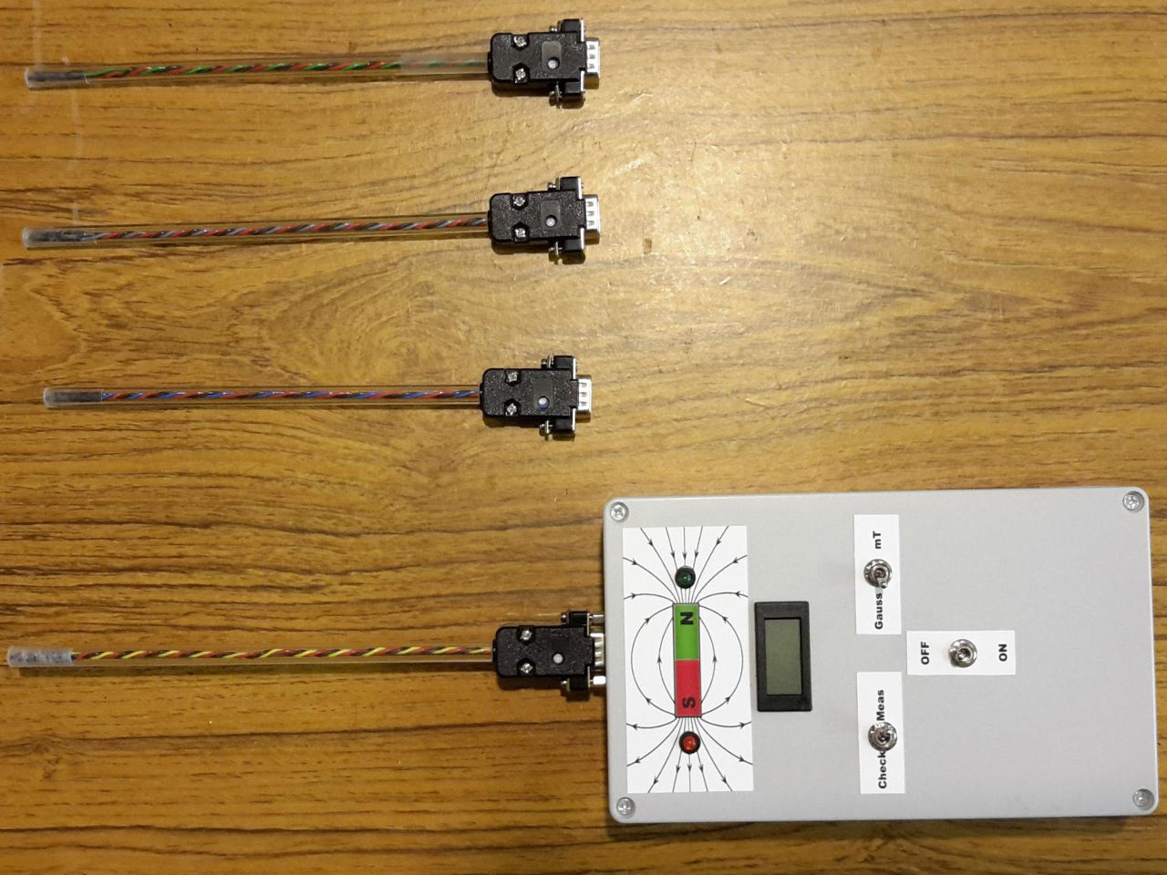
The enhancements are that this is now a four range unit, with interchangeable probes allowing varying degrees of sensitivity, reading directly in gauss or mTesla (10 gauss = 1mT or 1 millitesla). Ranges are 400, 640, 800 & 1540 gauss (40, 64, 80 and 154 mT).
| Range 1: | Yellow cored probe | ±400 gauss | (40 mT) |
| Range 2: | Blue cored probe | ±640 gauss | (64 mT) |
| Range 3: | Grey cored probe | ±800 gauss | (80 mT) |
| Range 4: | Green cored probe | ±1540 gauss | (154 mT) |
Initialising the meter
Innitialise the meter using the following steps.
- With unit switched OFF, plug in and secure required range probe, if not already fitted. (400, 640, 800 or 1540 gauss range)
- Switch unit ON, and the unit will read approximately zero, if the unit is in a nominally ZERO gauss field.
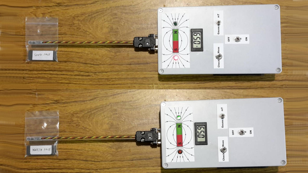
Doing a calibration check
Here we're doing a calibration check. The unit is using the 400 Gauss Probe (40mT) in operation, exposed to the North and South poles of the same magnet showing ± 59 gauss.
To do the calibration check, perform these steps.
- Switch "Check/Meas" switch to the "Check" position. This should result in the display reading approximately 400, 640, 800 or 1540, depending on the probe range If the unit is switched to the mT setting, this will be 40.0, 64.0, 80.0 or 154.0.
- If this is not the case, you may also have to adjust the Calibration Check Potentiometer (VR1 inside the box) which should be set to 4.5v as measured between the zero and 4.5v test points.
- With the test voltage set at 4.5v, adjust the small potentiometer in the probe plug, to achieve the desired reading (see schematics and photo of circuit board below). A range error of ±4.0, ±6.4, ±8.0 or ±15.4 gauss respective to each probe, equates to ±1% fsd.
Operating the meter
To operate the meter, follow these steps.
- With a North Pole near the left side of the probe, or a South Pole near the right side of the probe, the meter will read the magnetic field, with the Green LED lit above approximately 30 gauss (3 mT) field strength.
- With a South Pole near the left side of the probe, or a North Pole near the right side of the probe, the meter will read the magnetic field, with the Red LED lit above approximately 30 gauss (3 mT) field strength.
If needed, the PCB can be completely removed from the case, by unplugging everything, and removing the three screws.
Gauss/mT meter Schematic
The following is the main circuit. The DVM that I used allows for inputs not referenced to the meter power, by using a separate meter supply.
- R3 and R4 provide an elevated zero so the meter zero is actually 2.5V above the 0v rail.
- R1 and VR1 provide a 4.5V reference signal, which produces a +ve fsd input suited to each probe.
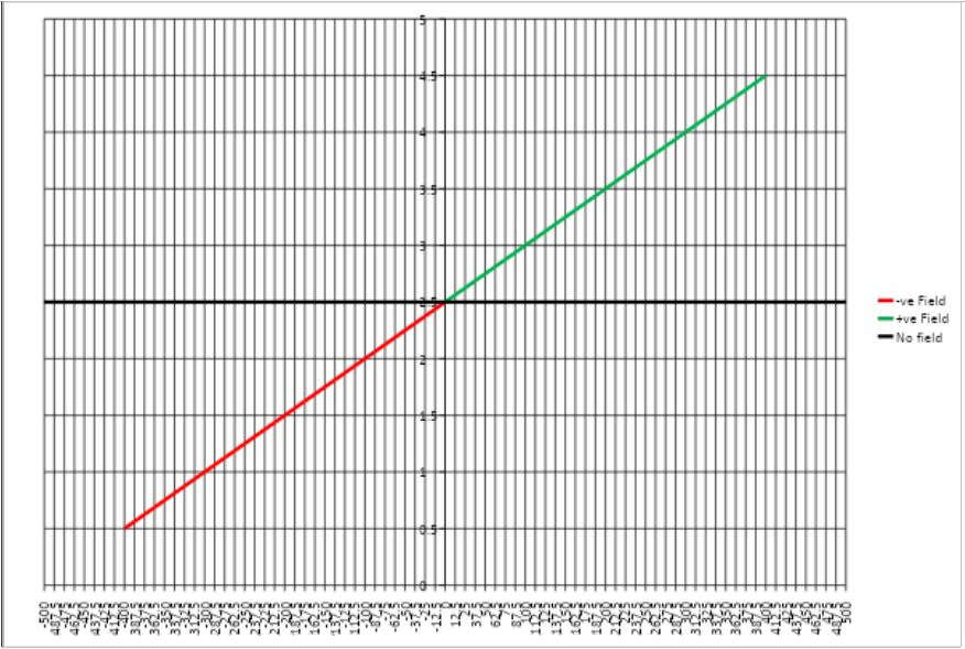
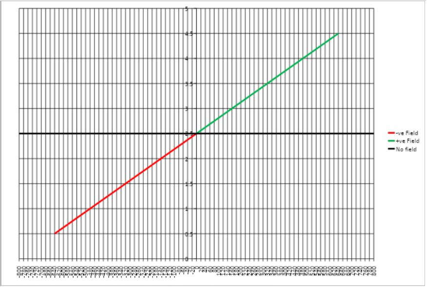
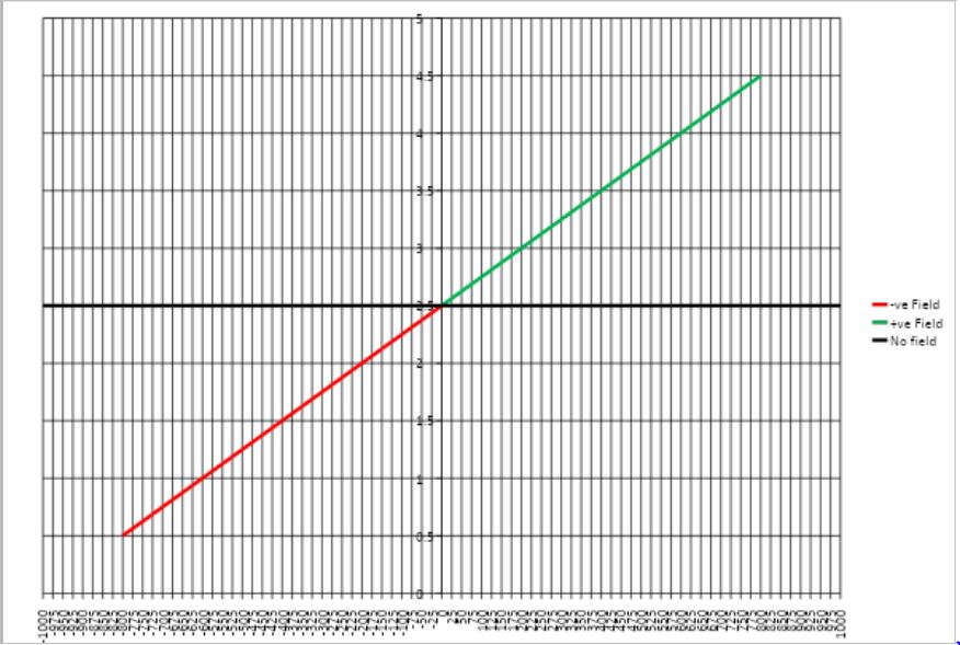
- The probes output ±2V (0.5 to 4.5V) from a nominal output of 2.5V in a zero gauss field, thus allowing the meter to read + or - from a nominal 0 gauss field.
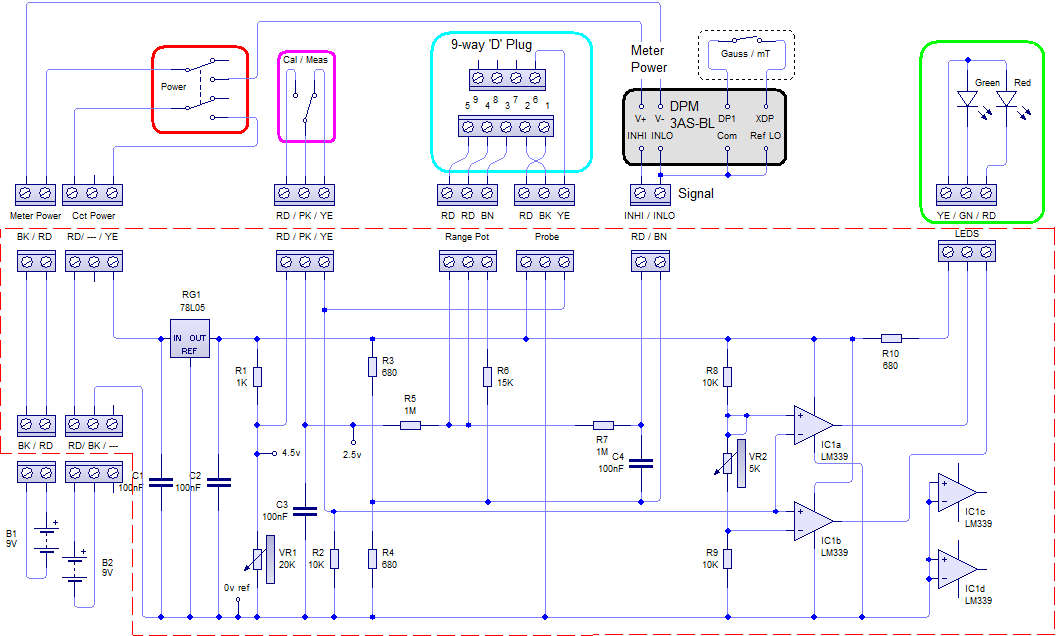
At a nominal Zero Gauss field strength, meter +ve input at the C3/R5 junction is ≈ 2.5V. VR1 sets the probe range Calibration Check Voltage at 4.5V (Equivalent to ≈ full scale) VR2 sets the Green/Red (N/S ) switching threshold for the LEDs.
Making the probes
For the probes:
- The range potentiometers VR3a to d (4 turn) are actually located in the probe plugs, so are changed automatically when a different probe is fitted.
- To accommodate all four ranges, an additional resistor (R6 = 15K) was needed.
- R5 (1M) and VR3 + R6 provide the input voltage divider to the meter, which has a maximum input of ± 200mV
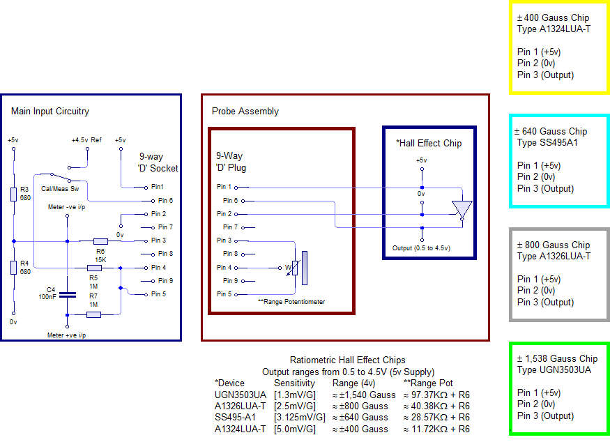
The internals of the 400G probe with the minute 4-turn pot are shown below, but construction of the other probes is the same. Range Pots are 50KΩ, except in highest range probe which is 100KΩ.
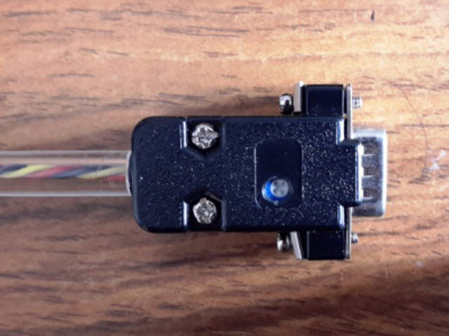
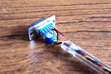
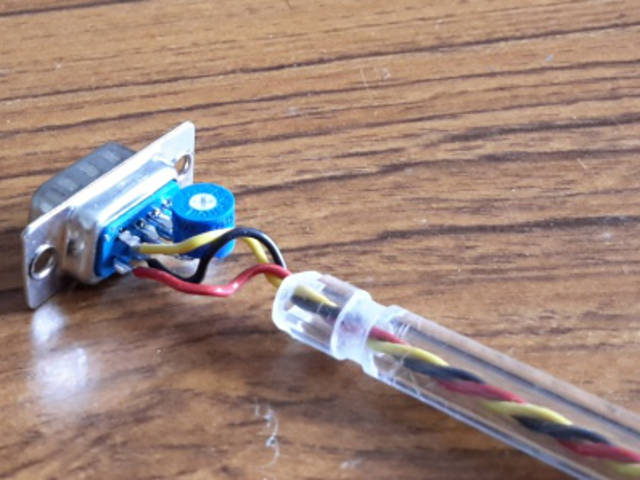
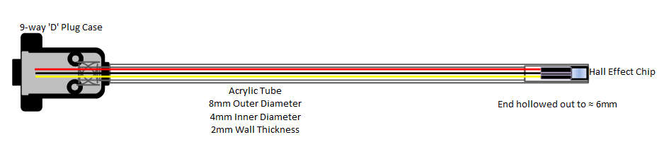
The plastic tubes are from "Simply Plastics" and are clear extruded acrylic tubes (8mm outer diameter, 2mm wall, 4mm inner diameter, 20cm long). The wires used are 7/0.2 wire in a twisted three core of Red: +, Black: - and Color: Output (resistor color codes used for output core where possible) Yellow(4) for 400G range, Blue(6) for the 640G range, Grey(8) for the 800G range, and Green(5) for the 1540G range.
The three wires are soldered to the Hall Effect chip and each covered in heat shrink insulation. The business end of the tube (where the chip is) was drilled out to accommodate the wiring and the chip, and the chip/wiring was just pulled into the end so the chip top was just level with the end of the tube (not glued in, as it is a tight fit). At the plug end, there is a section that has been filed down in a ring to suit the hole in the plug case, which it slots tightly into, and the very end of the tube is chamfered on each side to fit between the plug fixing pillars, preventing the tube rotating (no glue again, no need).
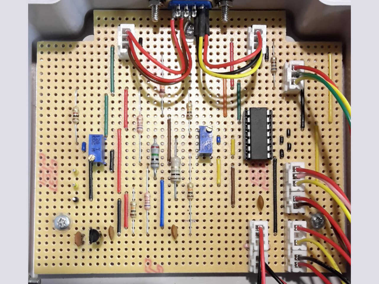
Laying out the circuit
Below is a picture of the veroboard the project was built on (everything plugs in, so can be easily removed for repairs).
The following diagram shows the Veroboard track breaks viewed from rear of the board (Left and Right top corners removed (4 tracks x 8 holes)). Overall, the Veroboard has 36 copper tracks (A to AJ), with 43 holes in each track (43 to 1).
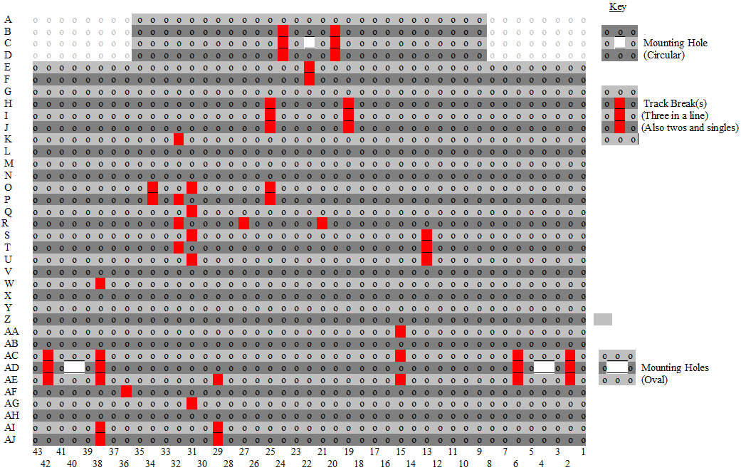
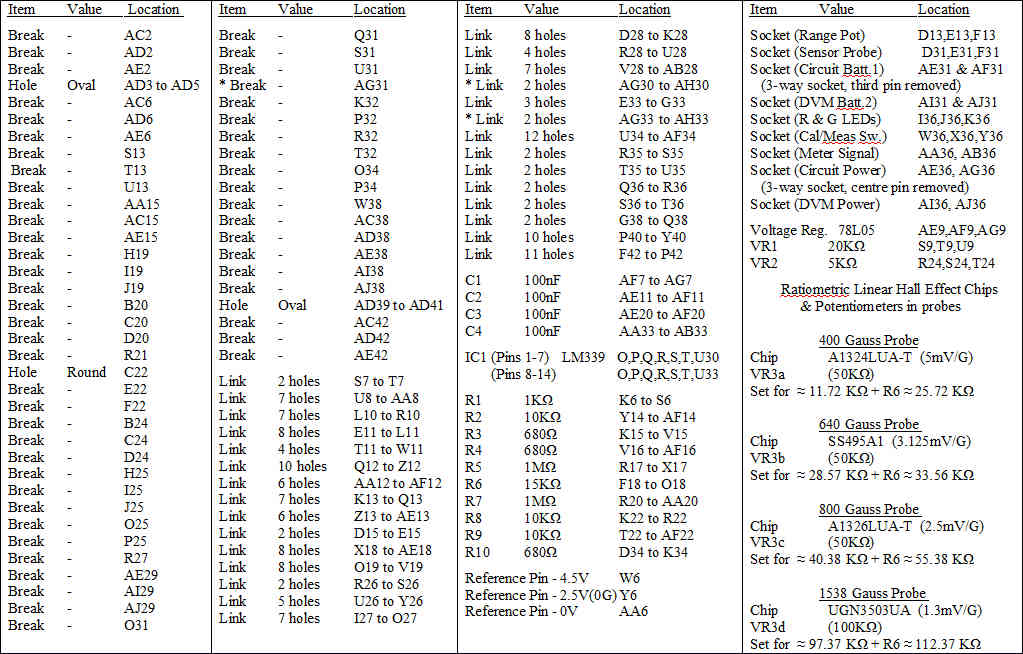
The following is the guide to i) Track Breaks and Fixing Holes, ii) Links, and iii) Component Placing. Note: Break at AG31 cut in error during development. Repaired via links AG30-AH30 & AG33-AH33 (see * in list).
Probe output graphs
Below are approximate output graphs for each probe.

|
Do you have a project you'd like to share on rimstar.org too? You're more than welcome to. Click here for details. |
|

