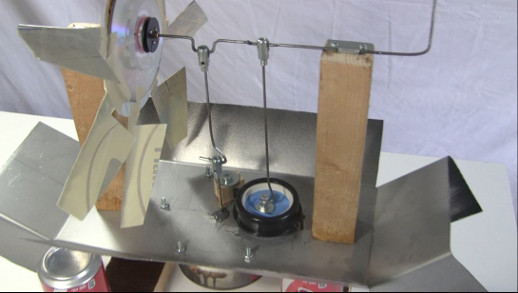
How to make a big Stirling engine for concentrated solar
I'm often asked for details on how to make parts of the big Stirling engine that I made for powering using concentrated sunlight. So here are as many details as I could think of. This isn't intended as a blueprint, but as a guide containing lots of good Stirling engine making tips and tricks.
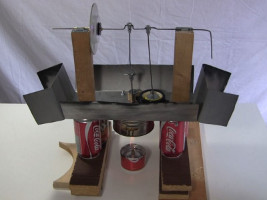
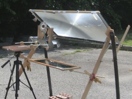
One basic design idea was to have a big enough big cylinder, the one containing the displacer, for the solar system to focus light onto. The other was to have a big metal plate as a heat sink at the top of that cylinder for cooling purposes, one that the outdoor air could flow over for cooling purposes.
The big metal plate
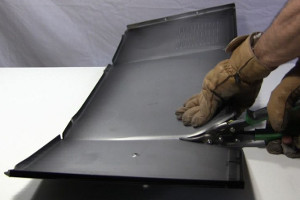
As you can see below, for the big metal plate I cut up and drilled the steel cover from a microwave oven. Others have used a PC case. Ideally would be to use aluminum since it's an excellent heat conductor but you'd have to find a sheet that's thick enough to be stiff enough since everything is mounted onto it.
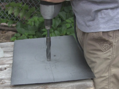
The displacer
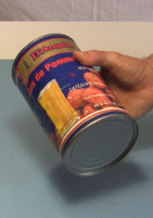
As shown below, a big diameter can was used for housing the displacer, an apple juice can. The diameter of the displacer itself was taken from this.
The displacer is an aluminum flashing metal disk with a clylinder of steel wool wrapped and sewn onto one side.
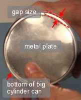
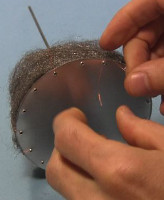
First a metal disk is cut from aluminum flashing. In the 2nd photo below the disk is held against the bottom of the big cylinder so you can see that it's cut smaller than the cylinder, to leave a gap around it for air to flow.
Then a shaft made from a length of clothes hanger wire is bolted to the disk such that the shaft is centered on the disk.
Finally, holes are drilled all around the circumference of the disk. These holes are for sewing the steel wool on, as shown further below.
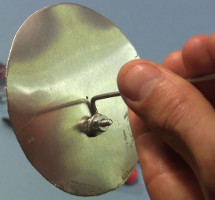
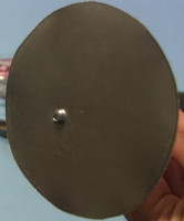
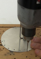
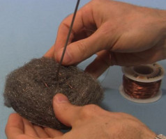
The steel wool can be found in hardware stores. If you can find stainless steel wool then that would be best since it would last longest. Below you can see it being cut with scissors and then being wrapped around the metal disk's shaft.
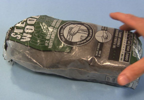
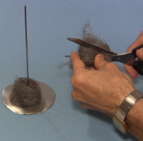
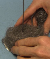
Finally, as shown below, the steel wool is fixed in place to the metal disk by sewing it on. To withstand the heat and last a long time, thin copper wire is used as the thread. The wire is tied to a hole in the circumference of the metal plate on one side, then pulled over and around the steel wool and tied to a hole on the other side.
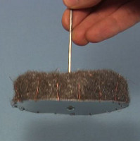
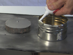
Before the displacer can be put in place, the big can previously mentioned above that houses it has to be prepared as shown below. It's cut to a height that is taller than the displacer with around 1 centimeter or 1/2 extra height inside. This is a rough number, guessed at, using the logic that when the cylinder is in the up position the externally supplied heat will be enough to heat up the volume of air that'll be between the bottom of the displacer and the bottom of the can.
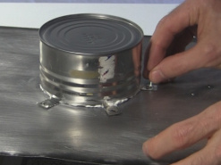
In the photos below, note the tabs cut and drilled at the open end. Matching holes are marked on the bottom of the metal plate and drilled.
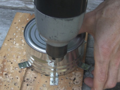
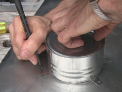
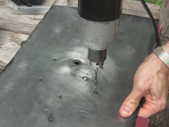
The photo below shows the top plate upside down and the displacer being inserted into the hole in the middle. The plate is sitting on books so that there's room underneath for the displacer's shaft.
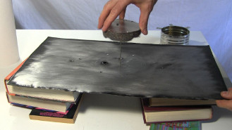
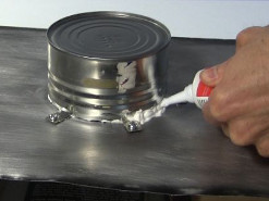
A generous amount of silicone chaulking, normally used for bathtubs and sinks and found in hardware stores, is put on the open edge of the cylinder. This chaulking is rated for 300F/150C. It's then lowered down over the displacer, making sure that the displacer is not touching the interior sides, and bolted in place. Extra chaulking is then put all around.
Linking the rods and crankshaft together for the Stirling engine - the linkage
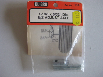
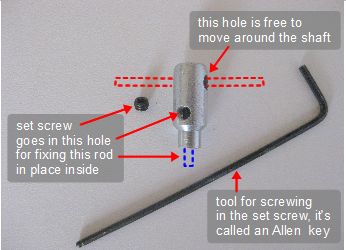
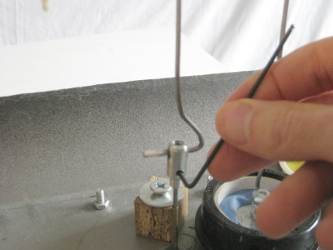
I linked the various rods and crankshaft together using the parts shown below. Normally they're used for the axles of model or RC aircraft and can be found in hobby stores. The rods and crankshaft are made of metal clothes hanger wire. The top has a hole through it horizontally big enough for a shaft to go and to turn freely. The bottom has a hole going up it vertically for a rod. The rod is fixed in place using a set screw. The set screw is screwed in through a hole in the side using an Allen key and presses the rod against the inside of the parts, holding the rod firmly in place.

The diaphragm (cold side)
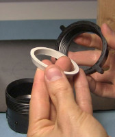
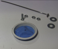
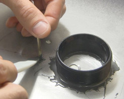
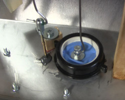
A flexible diaphragm was used for the cold side. Both a rubber balloon (blue) and the material from dishwashing gloves (yellow, shown in some parts of the videos) were used and both worked. Also as shown below, the diaphragm casing was made using ABS plumbing parts from a hardware store. This could of course be made using any cylinder but the nice thing about these plumbing parts is that the rubber diaphragm is glued to a rubber o-ring that is removable and changable should it wear down, or just not work well.
The finished big Stirling engine
The photo below shows all the finished parts in place. To see the Stirling engine in action, see the videos on the demonstration page.
