Communicating via laser to photoresistor
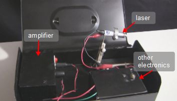
I'd previously made a laser communicator for transmitting to a solar cell but I'd been asked to also try transmitting to a photoresistor (also known as a photocell or LDR - Light-Depentent Resistor.) I came up with a circuit design that worked, and the resulting sound was much better than with the solar cell.
A video of it in action is given below.
Getting the best sound
If the laser light going to the photoresistor is too bright then it will become saturated and you'll hear a crackling sound from the output amplifier connected to the photoresistor. One solution to this is to dim the laser light by turning down the volume of the amplfier that feeds the laser as part of the laser communicator until you don't hear any more crackling. Then, since the sound is quieter now, turn up the volume at the output amplifier connected to the photoresistor so you can hear it better.
How to make the photoresistor circuit
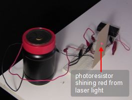
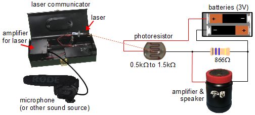
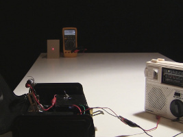
Below you can see the circuit on a breadboard as well as a circuit diagram. I've removed the photoresistor from the cardboard background (which you can see in the above photos) and plugged it directly into the breadboard instead for the photos below so that you can see it more easily. Note that in the actual circuit I've used a 1 kilohm resistor instead of an 866 ohm one since that's close enough and it's what I had.
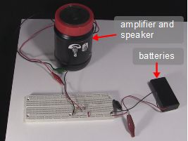
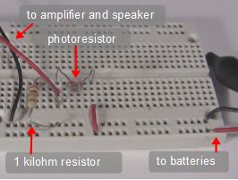
You may notice that the photoresistor and the resistor make up a voltage divider circuit. Also, the amplifier is in parallel with the resistor. That's so that the amplifier with get a voltage that's controlled by the fluctuating voltage across the photoresistor which in turn causes a fluctuating voltage across the resistor.
The main trick was to figure out a good value for the resistor. With the wrong value, the voltage across that resistor will fluctuate between a small range, so small that all the sounds coming out of the amplifier will sound the same. It's like craming a song into only a few musical notes. With the right resistor value, the voltage across that resistor will fluctuate across a larger range, and the amplifier will put out a wider range of sounds; it'll have more notes to represent the song.
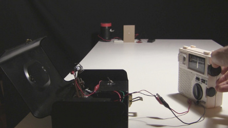
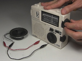
The first step to figuring out a good resistor value is to find out what the minimum resistance of the photoresistor will be and what the maximum resistance will be. To do that we transmit a representative sample of sounds using the laser communicator to the photoresistor while measuring the resistance of the photoresistor. In the photos below I first tune the radio to a radio station and then use the laser communicator to transmit what's coming from the radio station to the photoresistor as laser light. At the same time I'm watching the meter to see what the resulting resistances of the photoresistor are, looking for the lowest and highest values.
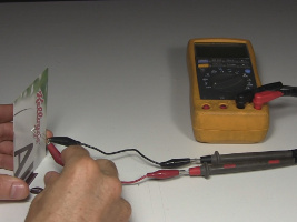
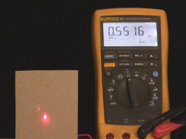
The result of the above test is that the photoresistor has values fluctuating from 0.5 kilohms to 1.5 kilohms. Note that your photoresistor may be different, as may be your laser, so you may get different results.
The next step is to calculate a suitable resistance.
One way to calculate a suitable resistance is to use something called the Axel Benz formula, which is that the resistance should be the square root of the minimum and maximum resistances of the photoresistor multiplied together.

So we multiply 1.5 kilohms by 0.5 kilohms, and get 0.75. Then we take the square root of it and get 0.866, or 866 ohms.
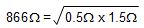
That 866 ohms is the value we should use for the resistor.
Calculated voltage ranges
The following is not needed for making this circuit. It's just two examples of calculating voltage ranges that the amplifier would get for two different resistances in order to illustrate how the correct resistor resistance makes a difference.
Let's say the resistor's resistance is 10 kilohms instead of 866 ohms. And let's say the laser is at its dimmest, causing the photoresistor's resistance to be 1.5 kilohms. Adding the two resistance together we get a total resistance of 11.5 kilohms. Using the formula to ohm's law, I = V / R, or the current equals the voltage divided by the resistance, we get that the current is 3 volts divided by 11,500 ohms, which is 0.26 millamps. We can now calculate the voltage across just this resistor again using ohm's law, V = IR, or the voltage equals the current multiplied by the resistance, which is 0.26 milliamps times 10,000 ohms, or 2.6 volts. So that's the voltage across this resistor, and this amplifier and speaker, when the laser light is dimmest.
Now lets do those calculations again for when the laser light is brightest, which we measured as around 0.5 kilohms. This time the current is 0.29 milliamps, and the voltage across here is 2.9 volts.
That means that over the range of brightness for the light coming from the laser while we're speaking into the microphone, the voltage will vary from only 2.6 volts to 2.9 volts, a range of 0.3 volts, not much, and so the sounds coming out of the speaker will all sound the same.
But we can fix that with a lower value for this resistor which we calculated above using the Axel Benz formula, 866 ohms.
Redoing the calculations for the range of voltages across here now with this new 866 ohm resistance value, we get a range from 1.13 volts to 1.9 volts, a range of 0.77 volts, much better than the previous 0.3 volts with the 10 kilohm resistor.
Video - Laser Communicator to Photoresistor/Photocell
The following video shows the above laser communicator and photoresistor in action, as well as the use of the Axel Benz formula.
