Make a USB power cable
Here's how to make a USB power cable when you need to power something from USB but you don't have a cable with the right connector for whatever you want to power.
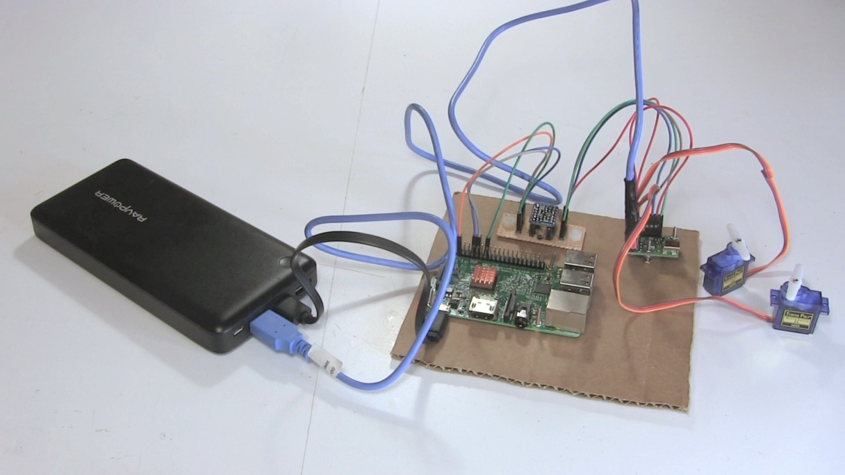
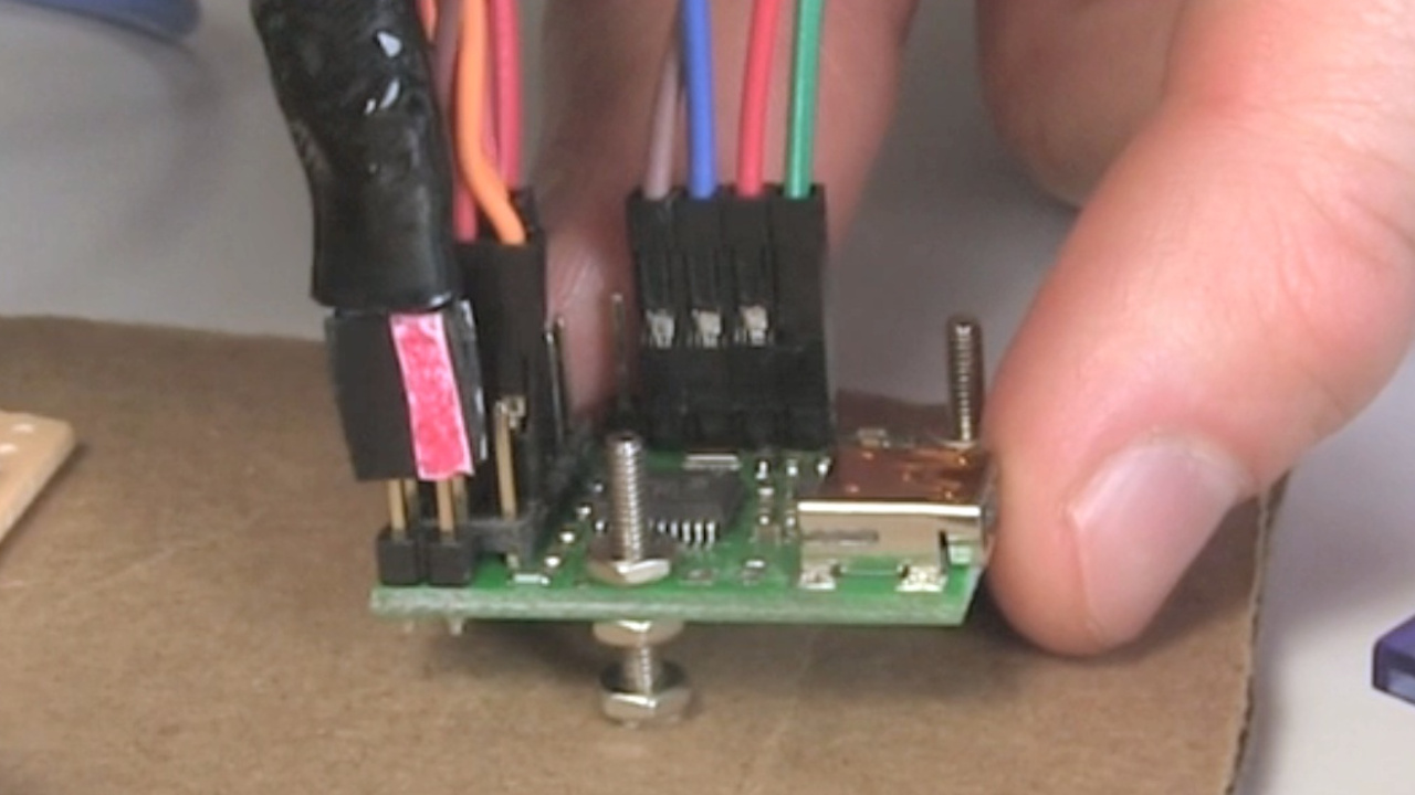
In my case I wanted to power a Maestro motor controller board to control some servo motors. My power supply was a RavPower USB phone charger/battery bank. The board had some male pin headers for the 5 volt input. So I went to a thrift/second-hand store and got a USB cable with a connector that would plug into the power supply. Then I replaced the other end of the cable with a female pin header to plug into the board.
Making the USB power cable
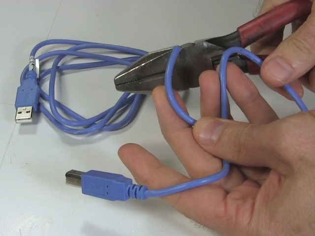
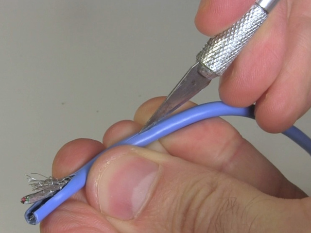
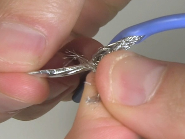
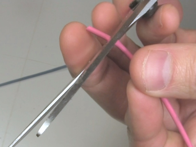
The first step was to cut off the unwanted connector. Then I used a sharp knife to make a slit along the jacket, being careful to not damage any wires inside. Be careful to not cut yourself. Then pull back the jacket. In my cable the wires were further covered by mesh and foil shielding.
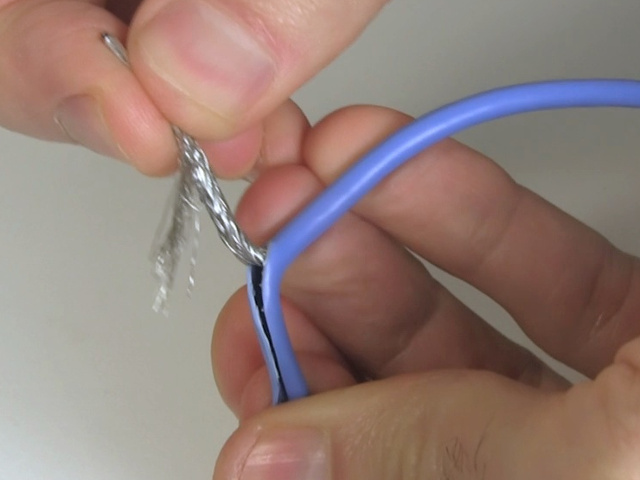
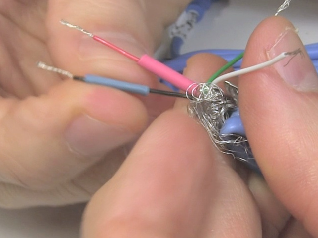
I pulled back the shielding to expose the wires inside.
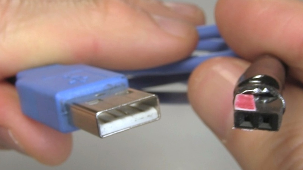
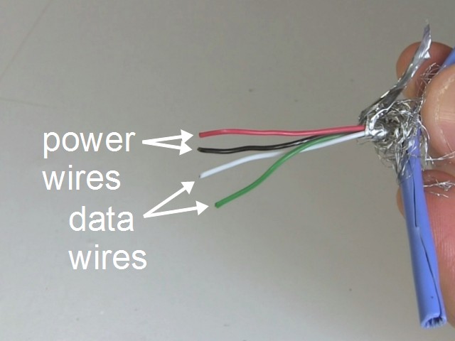
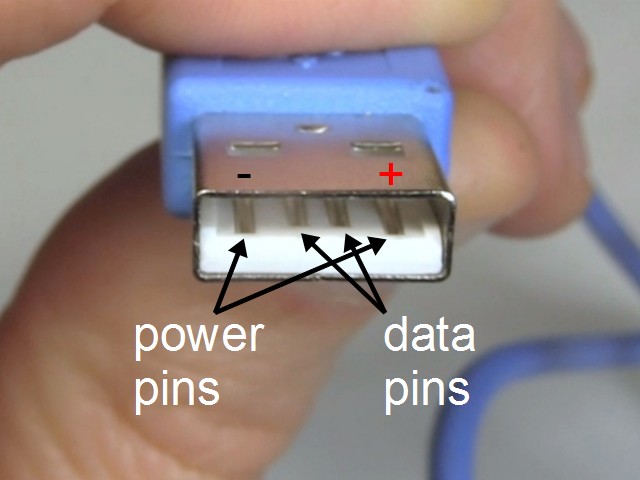
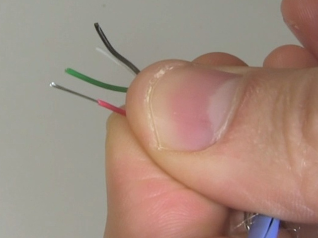
There are two power wires (red and black) and two data wires (white and green). Inside the USB connector, the power pins are the outer two and the data pins are the inner two.
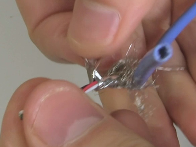
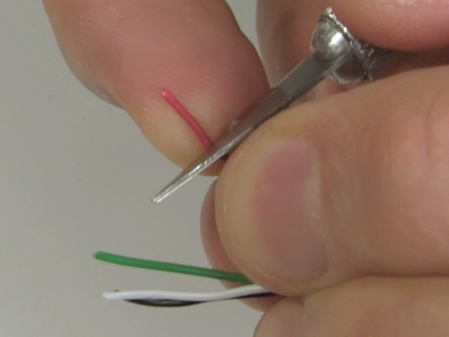
Using the knife again, I carefully cut a short length of insulation from the end of the red and black wires, and pulled it off. I did it using a knife because the tool I normally use for trimming wires doesn't work with such small diameter wire. If your tool does then you can use that instead.
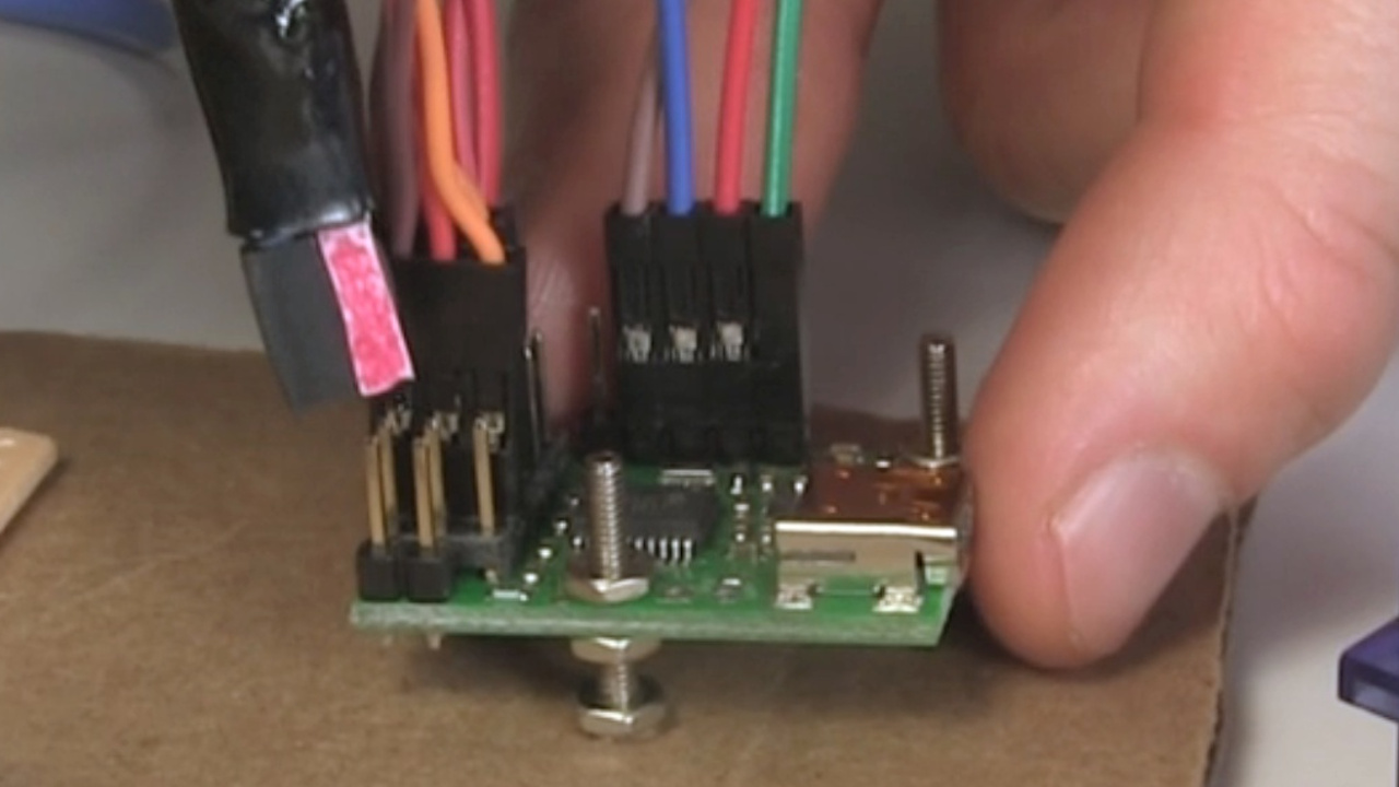
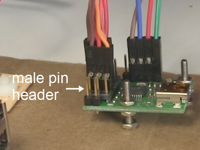
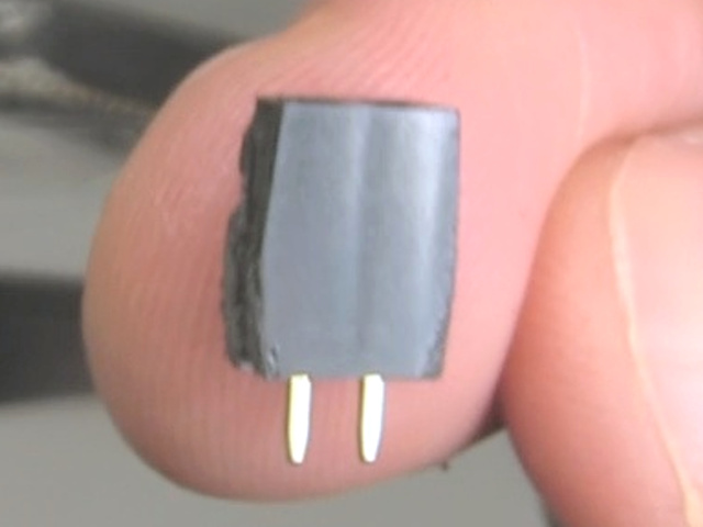
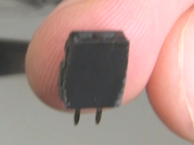
As I said, in my case I needed to plug into the two pins of the type shown below, called a male pin header. To do that I got a female pin header and cut out a two-pin header from it. If you're not familiar with doing that then see this page all about working with pin headers.
In preparation for soldering the pin header to the two data wires, I first cut some heat shrink tubing for both wires and and slid them onto the wires.
I then soldered the red and black data wires to the pin header, being careful to keep the heat shrink tubing away from the heat since I didn't want them to shrink while I was still soldering.
Then I slid the heat shrink tubing over the exposed metal where I'd done the soldering, and used a heat gun to shrink the tubing over the metal, insulating it.
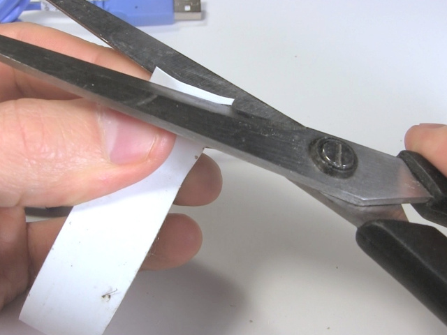
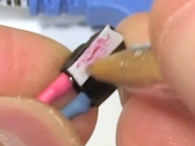
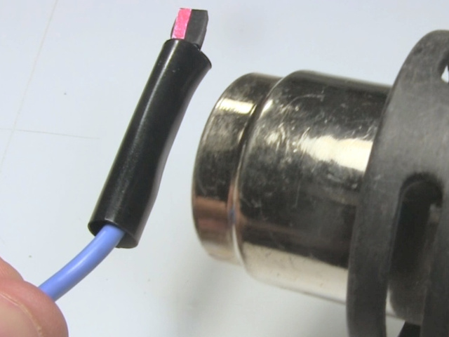
While I could still see which wire was red, and therefore which of the two connector holes was positive, I wanted to mark red on the connector somehow. One good trick is to use red nail polish, but I didn't have any. So instead I cut a strip of white tape, put it on the red-wire side of the connector, and painted it red using a red pen. If I'd had red tape then I could have used that instead.
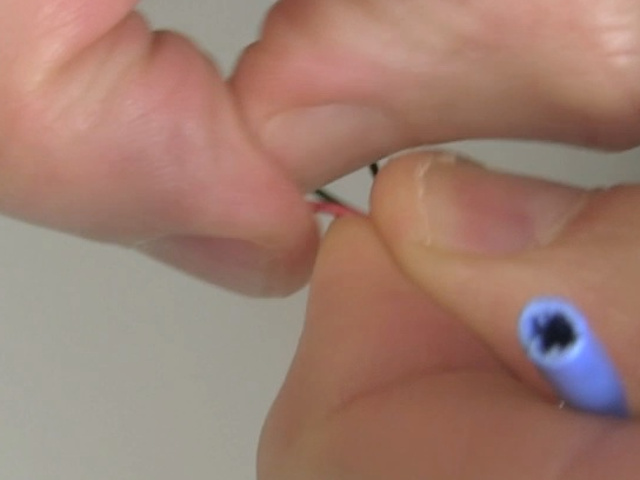
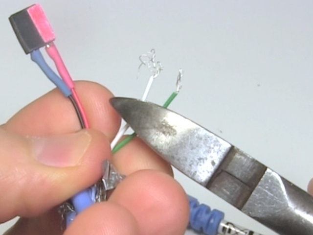
Since the data wires aren't needed, I cut them short. I could have left them like that but I wanted no chance of the metal in those wires touching together and sending a false signal. So I covered their ends in heat shrink tubing too.
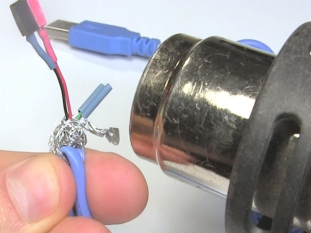
To finish up the end of the cable, I first cut some foil from a roll of the type of aluminium foil found in grocery/food stores normally used in the kitchen for wrapping food. I wrapped that around the wires since the original foil was no longer long enough.
Then I pulled back the mesh and the jacket.
However, that didn't cover the whole thing very well anymore, so I slid on a big diameter piece of heat shrink tubing that covered everything, and used the heat gun again to shrink it on.
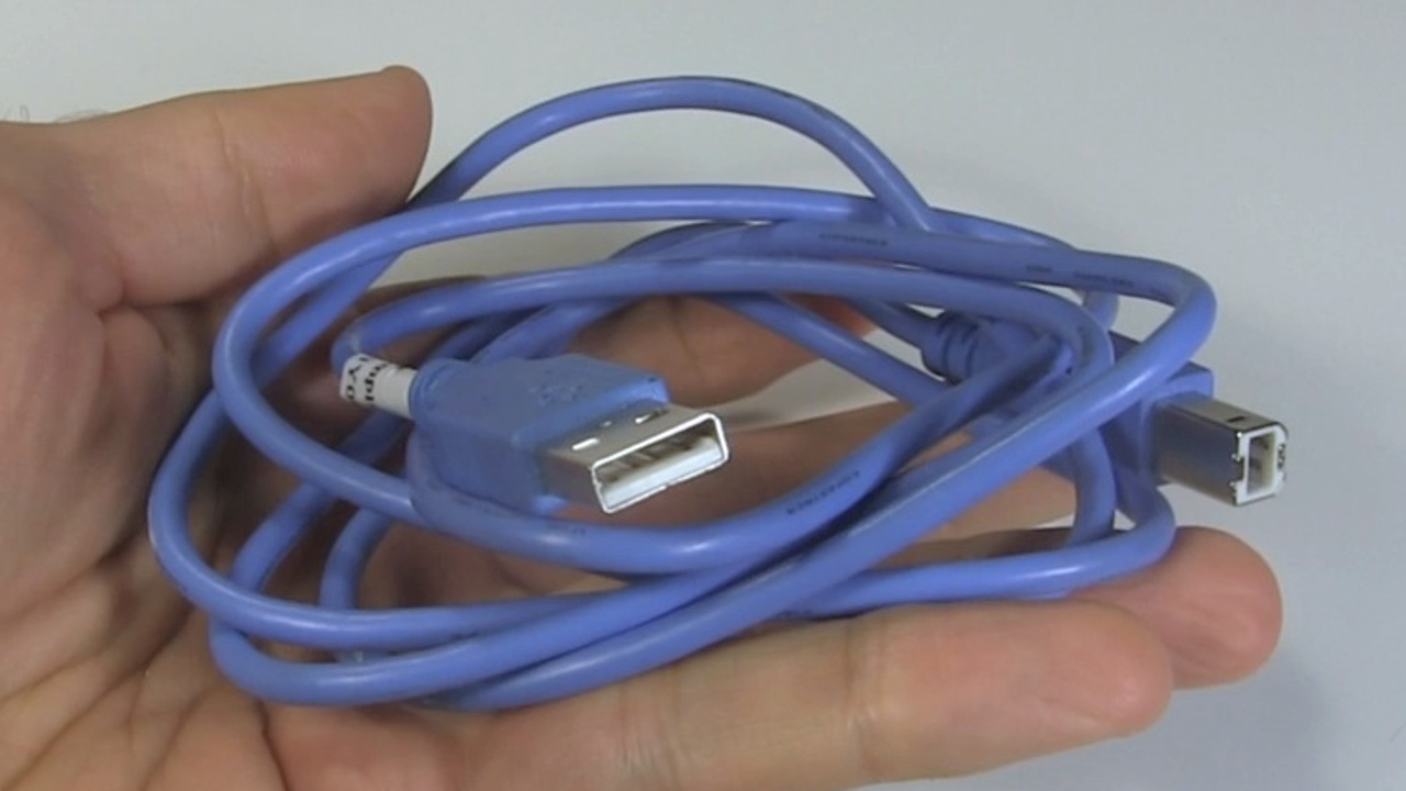
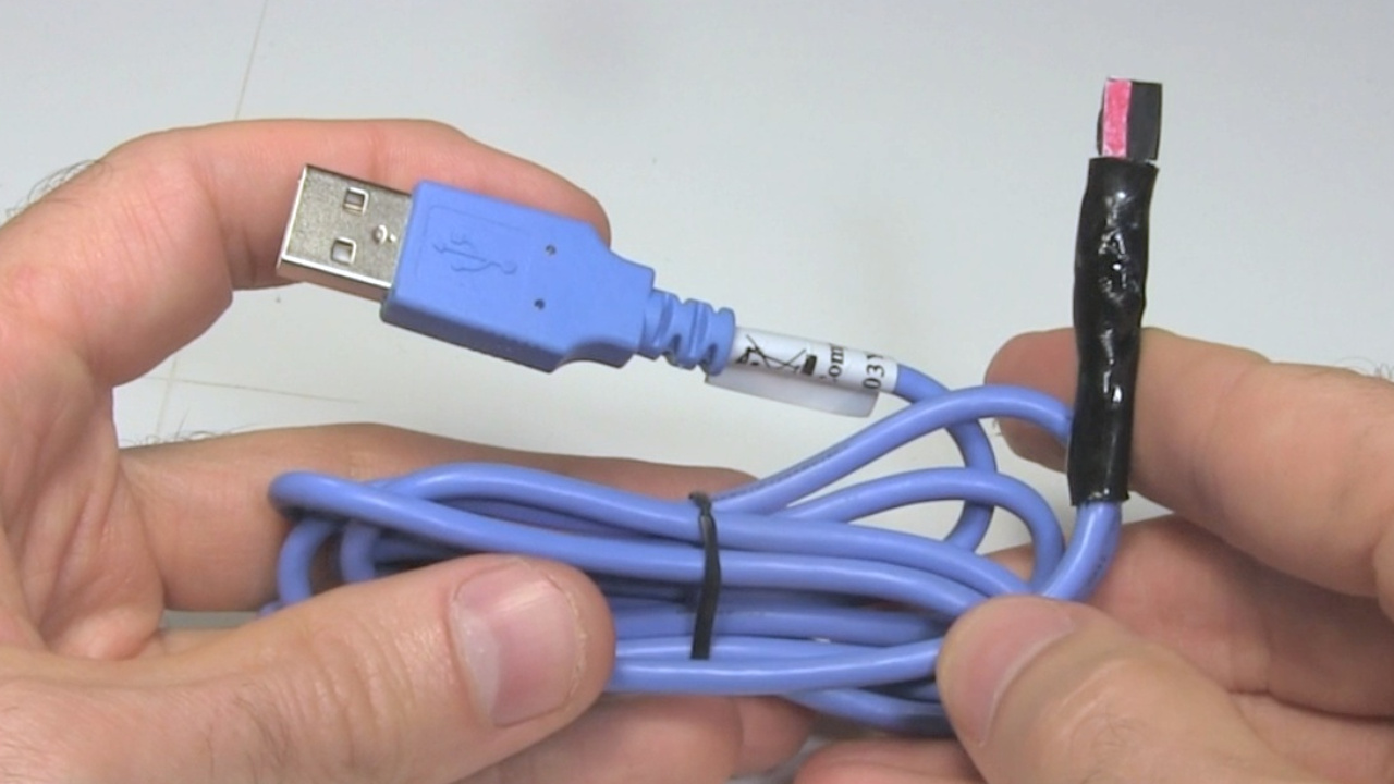
And here's the finished modified USB power cable.
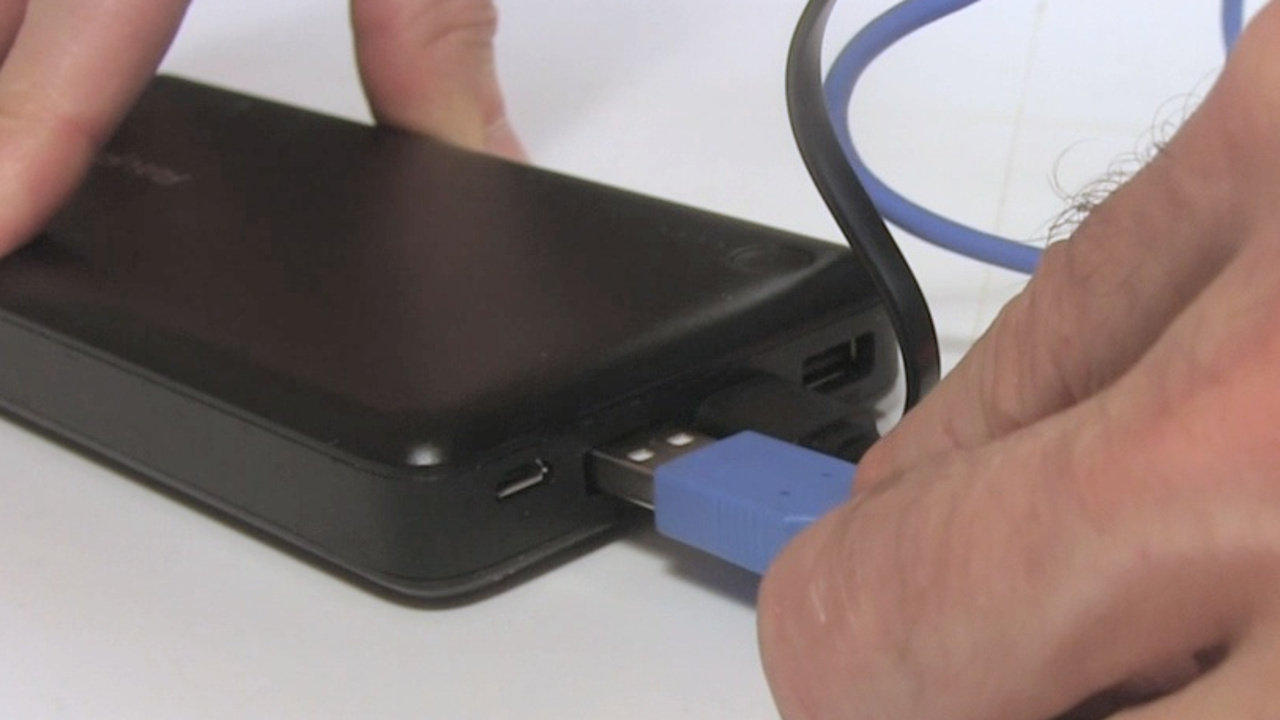
And here I plug one end into the phone charger/battery bank, and the other end with the new connector into the Maestro motor controller board.
Video - Make USB Power Cable
The following video shows all the above steps. It also shows using a meter to demonstrate which pins the power and data wires go to in the USB connector.
