All tests were done with the
Low Friction PVC Stator/Rotor.
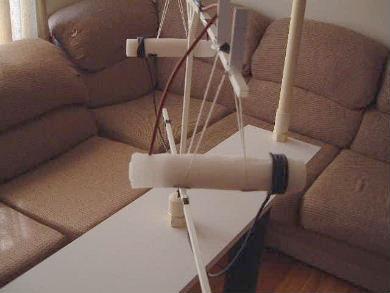
The setup - Clockwise from top left:
HV probe,
HVG10 High Voltage Power Supply,
ammeter (sitting on the red box for insulation), control box for power
supply, oscilloscope for reading voltage from HV probe.
 |
|
The first attempts were done with this heavy rotor since
it matched closely what Miklos was using. The top red wires are the high voltage
positive and the black bottom wires are grounded.
 |
|
Notice that the high voltage positive is connected to
the needles and the coiled wire is grounded. All tests with this heavy
rotor were done this way.
 |
|
I tried with the coil positioned 10cm from the needles and 8.5cm from the needles.
I turned the voltage all the way up to 57kV at which point the current was
around 50uA. I tried with the rotor in various starting positions with respect
to the stator. Given this high current I figured there was no point in raising
the voltage higher. At no time did the rotor move. My guess was
that the rotor was too heavy so I switched to a lighter rotor (see next).
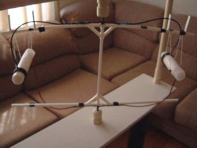
The lighter rotor. Once again, the red top wire is
high voltage positive and the black bottom wire is grounded.
 |
|
The candle is suspended using string. You might think
that given the string's location between the needles and the coil it might
interact electrically. It showed no signs of doing so and from experience
with this string in the past I figured it wouldn't.
 |
|
I tried all the same things as with the heavy rotor and got the
same null results.
I then switched the polarity such that the needles were now grounded and the
coils were high voltage positive. This makes sense since the needles are
sharp points embedded in the wax next to the wick whereas the coil is made
of 18AWG wire or thicker and is fully insulated with no sharp points. This
turned out to be the case as I was now able to turn the voltage all the way
up to 75kV (the most my power supply could do) with only around 15uA of current.
See the following picture.
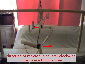
The black top wires are high voltage positive and the
red bottom wires are grounded - the opposite of what was previously done.
 |
|
I got movement! BUT... only at certain positions along the arc
of rotation and in both directions depending on where it was when voltage
was applied. Also, it would do so only at around 75kV, so very very high
voltage was needed. The most likely reason is coulomb forces -
attraction and repulsion balancing out. See the following.
Moved counter clockwise if started at this position.
Movement stopped when rotor arm was 90 degrees to the stator bar across the
top.
 |
|
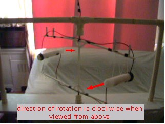
Moved clockwise if started at this position.
Movement stopped when rotor arm was 90 degrees to the stator bar across the
top.
 |
|
Click on the above pictures for QuickTime movies of the movement
(approximately 1.5Meg each).
If you don't have QuickTime you can download it
here.
The likely explanation is that when the rotor arm is close to
90 degrees then the high voltage wires that follow the rotor arm on
either side interact unevenly with the stator bar above them in terms
of electrostatic attraction and repulsion. The closest way to balance
out is to rotate the remaining amount to 90 degrees with respect to
the stator bar when the forces will then be balanced. The reason the same
thing doesn't happen when the polarity is reversed is that with the
high voltage on the needles instead of on the coil, there is too much
current flowing to get the voltage up to 75kV.
In any case, the result is that the candle devices
themselves are not producing any noticable thrust.

