Wind shielded scale
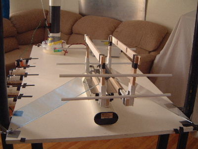
This is a test rig for testing small, moderate force devices that produce some form of wind that could affect measurements. Though many different scales can be used, this one uses a triple beam scale. The shielding is done with lucite (similar to plexiglass). Lucite was chosen because it was handy, non-conducting and transparent.
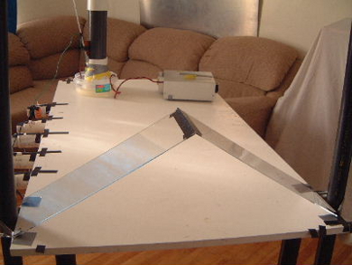
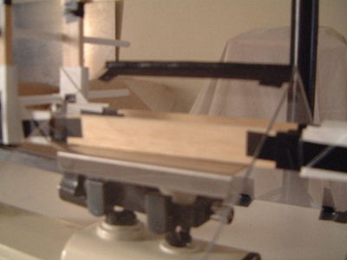
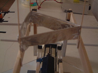
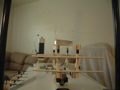
The basic idea was that the device would be fixed to the pan of the scale somehow so that when the device begins to produce a force, the force would register on the scale. However, since the device can produce a wind that could affect measurements, a lucite shield was placed between the device and the pan of the scale. The shield deflects the wind elsewhere. The shield is not attached to either the device or the pan and so would not affect measurements. The trick was to somehow have the shield between the device and the pan while still having the device attached to the pan. This was done by putting a frame between the device and the pan, with the device fixed firmly to the top of the frame and the bottom of the frame sitting on the pan. The frame was built such that the shield could fit through it without touching it. The following pictures illustrate this.
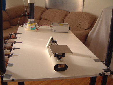
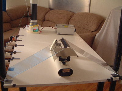
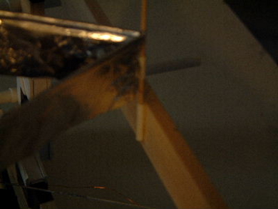
The first device tested using the test rig was a lifter. The following pictures show how the lifter was mounted in the test rig.
To actually test the device, the weight of the test rig plus device is first measured and noted as is. In the case of the triple beam scale this involves manipulating the scale's weights such that the pointer on the righthand side is zeroed. Once zeroed, the sum of the values indicated at the positions of the scale's weights indicate the weight (e.g. 245.1 grams).
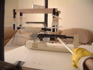
The device is then charged up such that it produces the force to be measured. Since it has produced a force, the pointer on the righthand side no longer is zeroed, the weight has changed. So the scale's weights are manipulated again so that we can note the new weight (e.g. 242.6 grams). Since voltage is applied during this time, a rubber glove and a long plastic stick are used to manipulate the scale.
The difference between the two noted weights is the weight change (e.g. 245.1 - 242.6 = 2.4 grams). This is the amount the weight that the lifter can lift for the given voltage. The following picture shows the scale's weights being manipulated while voltage is applied.
Testing the Test Rig
Two tests were done to prove the usefulness of this test rig. Both involved use of a lifter that can actually lift its own weight. Note that at this time (December 29, 2001) I have no way of measuring the voltage that my power supply is putting out at any time though it is supposed to be adjustable between 50kV and 150kV. So instead I will make note of what position the dial was at on the power supply. The dial has markings in the range of 1 to 100 though not all of the range is useful.
The first test was just to see if the measurments made represented reality. To do this I first tested the lifter without the test rig. The following data was obtained:
- The weight of the lifter: 2.1 grams +/- .1 grams
- Voltage at which the first leg lifts: 58/100
- Voltage that all legs are lifted tough without full tension on the tethering threads: 64/100
- Voltage where it is stable with full tension on the tethers: 67/100
I next put the lifter on the test rig and measured the weight at each of the above voltage levels.
- Weight of the full test rig with device attached to top of frame: 245.1 grams
- With voltage at 58/100, weight was: 242.7 grams, a 2.4 gram weight loss
- With voltage at 64/100, weight was: 242.2 grams, a 2.9 gram weight loss
- With voltage at 67/100, weight was: 242.0 grams, a 3.1 gram weight loss
The forces measured while on the test rig using voltages that can produce lift were all slightly in excess of what is required for the lifter to lift its own weight. As voltage increased, measured force increased. So far the test rig looked reasonable.
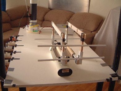
The second test was to see if any wind from the lifter could affect the scale. In other words, was the shield effectively shielding the wind? To test this I again used a lifter, but this time with the lifter not attached to the frame in any way. For this I sat 4 posts on the table and tethered the lifter to these posts. When the lifter lifts, there should be no movement on the scale. The following picture shows the setup.
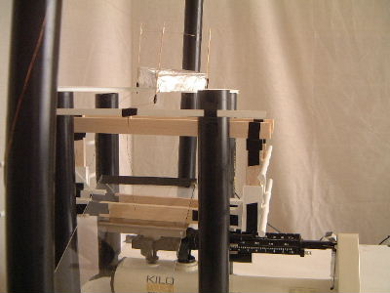
The result was that there was no movement on the scale.
