Off grid solar power system on an RV (Recreational Vehicle) or motorhome - Page 1
|
|
|
|
This is not your normal motorhome solar kit and installation (unlike Harvey's here.) This is the equivalent of an off grid system for a cottage. Howver, it also had additional complications not found in a cottage such as a 240VAC, 50amp capable receptacle for shore power that has to work with a 120VAC, 30amp inverter, the small bays in which the comparatively large parts have to fit, the rubber roof where wires have to run while still letting someone walk around to clean panels, increased shading issues due to frequent parking under trees, ... It was interesting and different enough to warrant documenting here.
Special thanks to Open Roads RV in Stittsville, Ontario for all their help and the use of their warm garage for doing this project during our cold winter months.
If you need a very simple layman's explanation of solar systems then you can first have a look at this "How it works" page.

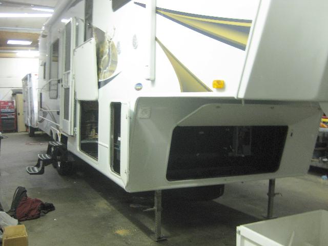
Table of Contents
The parts to be installed (on page 1)
Figuring out where to put things and mounting the inverter, E-Panel and charge controller (on page 1)
Wiring the solar panels and running the cable into the E-Panel (on page 2)
The AC wiring and making a 240VAC outlet work with a 120VAC inverter (on page 3)
Wiring the Outback turbo fan for sealed inverters (on page 3)
The battery bank, battery temperature sensor and venting (on page 3)
Powering DC Loads (on page 4)
Controlling and monitoring - Outback Mate (on page 4)
The parts to be installed
The parts were selected for the customer by a solar company in another city and bought before the customer had discovered us and then contacted us to do the installation.
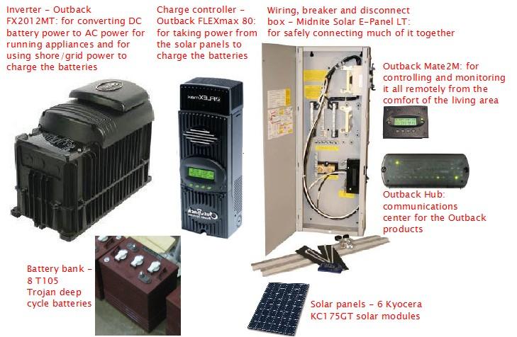
The solar panels, 6 Kyocera KC175GT panels, had already been mounted on the roof by the mobile home vendor but it was my job to wire them together and connect them to the rest of the system.
Figuring out where to put things and mounting the inverter, E-Panel and charge controller
The first thing I did was to figure out where the parts would go. Not only was fit a consideration but so was where the wires would have to run as the various components would be highly interconnected. Also important was that the cables going between the inverter and the battery bank had to be kept as short as possible (under 8 feet as a rule of thumb.)
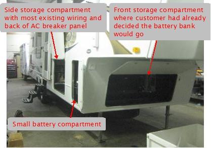
There was already a small 12 volt battery in the small battery compartment. This was used to power all the DC loads and was kept charged by shore power. I was told it was going to be removed and so the inverter could go there. Experience told me it would be a nightmare to do all the wiring in the confined area, plus there would be a lot of wiring going back and forth to wherever the other components would go.
So I looked in the side storage compartment.
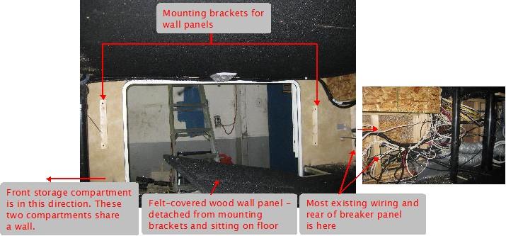
Both side walls were made up of removable felt-covered wall panels so I removed those first. They were screwed to various mounting brackets all around their peripheries. I quickly discovered there wasn't enough depth behind the wall panelling for anything and the customer wanted the full use of the remainder of the compartment for storage, so that was out.
That left the front storage compartment where the customer had already built a battery box to fit. After some measuring I found there would be enough room above and to the right of his box.
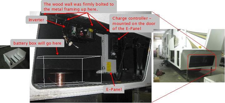
In the above photo you can see the inverter and the E-Panel with charge controller on it mounted on the back wall of the front storage compartment. This back wall is also a wall for the side storage compartment (see Side storage compartment photo above.) In that compartment, this wall is normally hidden behind one of the felt-covered wall panels I'd removed and there were a bunch of wires and pipes there. So I had to be careful when drilling through this wall so as not to damage anything.
Reinforcing the back wall
The back wall is actually about 1/2" thick wood and was not anchored firmly enough in place to support the weight of the massive inverter. Luckily the top part of it did overlap a part of some rigid steel framing so I drilled holes through the steel framing and through the wood. In each hole I put a bolt and washer against the steel with a large washer/lock washer/nut on the wood side.
Mounting the inverter on the back wall
The inverter has four mounting holes at its corners. I wanted to pre-drill matching holes in the back wall so I first laid the inverter on a piece of cardboard on the floor and marked the mounting holes on the cardboard. I then temporarily taped the cardboard to the wall and drilled the holes through the wood using the marks on the cardboard as precise guides. Next I prepared four sets of bolt/lock washer/large washer/nut and found someone to help me. I held the massive inverter in place on the wall and pushed each bolt through the mounting holes and through the holes in the wall while my helper, in the side storage compartment, attached the lock washer/large washer/nuts firmly on the other side.
Preparing and mounting the E-Panel
I next laid the E-Panel on the floor and worked out where I'd need holes for various cables and wires to enter. I used every available knockout and even made one using a stepped drill bit, an expensive bit but indispensible for making holes like this. I put strain reliefs in each hole.
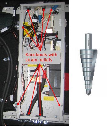
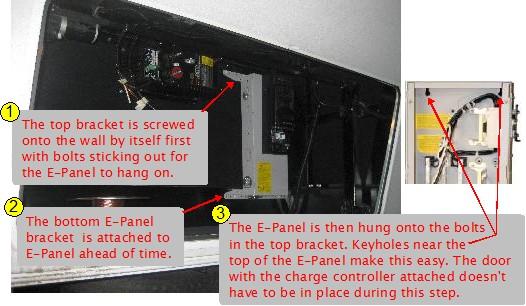
The beauty of the E-Panel is that the door and whatever's mounted on it doesn't have to go on until you need it to later. Then it's just hung in place and screwed shut when finished. As the following photo illustrates, even mounting it on the wall is a simple three step process requiring only one person (again, the door doesn't have to be attached during this.) (Can you tell I really like this product? :-))
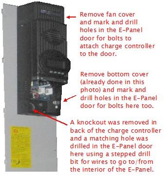
Next, the charge controller was attached to the E-Panel door, even though it wouldn't be needed until the wiring for the solar panels was done. I mounted it as high as I could so that the wiring that will run into it later would not interfere physically with the thick battery cables and shunt in the E-Panel.
|
|
|
|
