Off grid solar power system on an RV (Recreational Vehicle) or motorhome - Page 3
|
|
|
|
Table of Contents
The parts to be installed (on page 1)
Figuring out where to put things and mounting the inverter, E-Panel and charge controller (on page 1)
Wiring the solar panels and running the cable into the E-Panel (on page 2)
The AC wiring and making a 240VAC outlet work with a 120VAC inverter (on page 3)
Wiring the Outback turbo fan for sealed inverters (on page 3)
The battery bank, battery temperature sensor and venting (on page 3)
Powering DC Loads (on page 4)
Controlling and monitoring - Outback Mate (on page 4)
The AC wiring and making a 240VAC outlet work with a 120VAC inverter
In the RV or motorhome world, whenever you plug into the grid to get power we say you are plugging into "shore" power. This term comes from the boating world where you plug in when you get to shore (land.)
This motorhome accepts either 120 volts (V) AC or 240V, at 50 amps. The problem with this system was that the Outback 2012 inverter takes only 120V and puts out only 120V (i.e. never 240V.) Also, the inverter's maximum input and output is only 30 amps. So somehow I had to make this all work even when the shore power is 240V.
Here's how the wiring worked in this motorhome before changes were made.
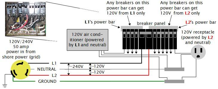
The thing to realize is that all the breakers in the breaker panel and hence all the loads in the motorhome are 120V. The breaker panel doesn't even allow a 240V appliance. There's no way to put in a breaker that is connected to both L1's power bar and L2's power bar at the same time, unlike with breaker panels in houses which do provide a way.
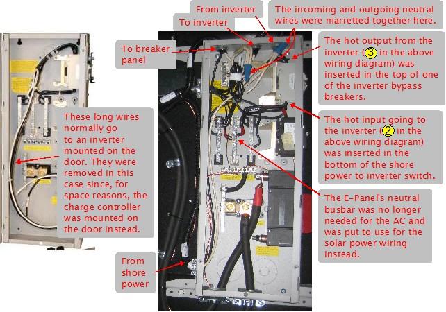
So the solution to make it work with the inverter was simple. For the input to the inverter from shore power, I took L2 and neutral and sent those to the inverter. For the output from the inverter I sent this to the breakers that L2 had previously powered. Meanwhile, I left L1 unchanged.
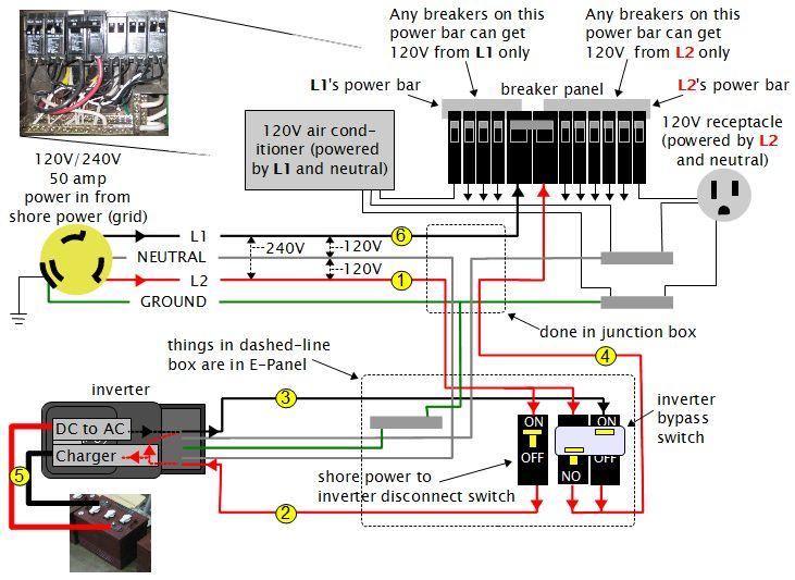
As shown at bottom/left in the above wiring diagram, when connected to shore power, the Outback inverter passes thru the shore power directly to the output (1, 2, 3, 4), using any leftover to charge the batteries as needed (1, 2, 5). When not connected to shore power, the inverter converts DC power from the batteries to AC power to feed to the output (5, 3, 4), i.e. it's inverting.
That means that the breakers previously powered by L2 would get their power from shore power when the motorhome was plugged into shore power and would get their power from the inverter when the motorhome was not plugged into shore power (e.g. when it was on the road). This also means that the breakers powered by L1 would get power only when plugged into shore power (6). When not plugged into shore power whatever loads were connected to the L1 breakers would not work. This was actually the case for all the breakers before this solar system was installed.
This also addressed the 30 amp maximum output issue with the inverter. Since the inverter would only ever power the L2 half of the breaker panel it would never be asked to supply more than 30 amps.
Notice that the neutral wire has been split into two independent wires that both go to the inverter. This is a special requirement of the mobile versions of the Outback inverters.
The inverter bypass switch (bottom/right in the above wiring diagram) allows the inverter to be removed from the circuit in case the inverter breaks down. It puts things back the way they were before. It consists of two breakers that work together. Notice that the left one is upside down, so for it, up is OFF and down is ON. This is just the opposite of the right breaker. The above diagram shows the normal position with the left breaker OFF and the right breaker ON, meaning that the output of the inverter is going to the breaker panel. If it were in the down position then the left breaker would be ON and the right breaker would be OFF, meaning shore power would be going directly to the breaker panel.
Wiring the Outback turbo fan for sealed inverters
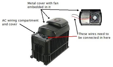
The Outback FX2012MT inverter is a sealed inverter and comes with a fan in the cover that has to be wired up. The difficulty is that the fan is embedded in the metal cover and the wires go in the AC wiring compartment. This is difficult because the AC wiring compartment cover is partially under the metal cover. So you need to connect the wires in the AC wiring compartment while holding on to the metal cover, then screw on the AC wiring compartment cover and then screw on the metal cover.
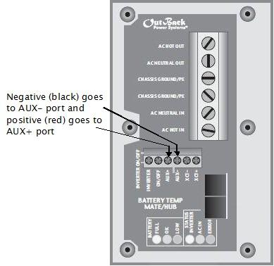
The fan is a 12 volt DC fan. The negative (black) wire goes to the AUX- port and the positive (red) wire goes to the AUX+ port. The inverter's default setting is to use the AUX port for the fan so no programming is needed, though I always check. This is done from the Outback Mate after everything has been installed (the inverter runs off of the batteries so you'll need to get at least that far before any programming can be done.)
The battery bank, battery temperature sensor and venting
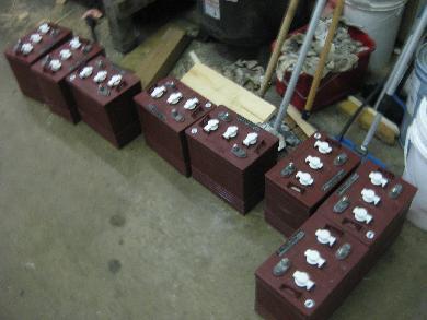
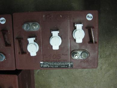
The batteries were 8 Trojan T-105 Plus deep cycle flooded lead acid batteries. They are 6 volts each with a capacity of 225 amp hours (AHr) at the 20 hour rate. This means that they will deliver 225 amps total if discharged over 20 hours.
Since the Outback FX2012MT inverter is a 12V inverter, I had to wire the batteries together to make up a 12V battery bank. To start with, each battery is 6V. Just like with solar panels, connecting batteries in series (positive to negative) causes the voltage to add while the current (AHr) stays the same. So I connected the positive of one 6V, 225AHr battery to the negative of another 6V, 225AHr battery to end up with a 12V, 225AHr series string of batteries. That gave me my 12V. So I repeated this with the remaining 6 batteries giving me 4 separate 12V, 225AHr series strings. Since connecting them further in series would give me too high a voltage, all that was left was to connect these strings in parallel. Connecting in parallel leaves the voltage the same but the current (AHr) adds. So now I had 4 parallel connected strings for a total battery bank size of 12V, 900AHr (4 x 225). Unfortunately I was too busy installing the system to remember to take a photo but the following diagram illustrates what I did.
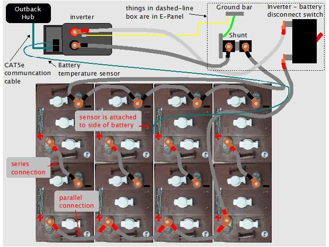
All the very thick grey cables shown above are 4/0. 4/0 is about 12mm (1/2") in diameter. It needs to be around that thickness in case there is a short in the battery wiring somewhere. If a 900AHr battery bank starts dumping due to a short then the current could be hundreds of amps so thick wiring is need to handle that current without melting and starting a fire.
The inverter - battery disconnect switch is a 250 amp DC breaker. Besides safety, it's also used to disconnect power from the inverter since the inverter runs off of battery power (the Outback inverter will also run off shore power if shore power is connected when this inverter-battery disconnect switch is turned off.)
The temperature sensor is glued (and I also strapped it) to the side of a battery somewhere in the middle of the battery bank. It gives the inverter some idea of the temperature of the batteries so that it can compensate appropriately when charging.
Also of note above is the way the battery bank's negative terminal is grounded. This is done indirectly using the green thick 4AWG wire in the E-Panel between the shunt's busbar and the ground bar (see wiring diagram above.) Theoretically the wiring in the path to ground for the batteries should be the size of the largest wire used in the batteries, 4/0, which is about 12mm (1/2") thick. This is a little unreasonable and so the Ontario Electrical Code says it would be safe enough to use at least 4AWG wire.
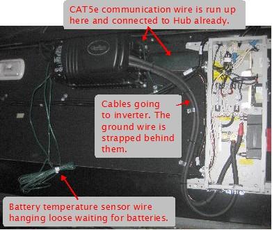
Lastly, note the CAT5e communication cable connecting the inverter to the Outback Hub. This is so that the inverter can be monitored and controlled from the Outback Mate which I installed on a wall inside the motorhome's living area.
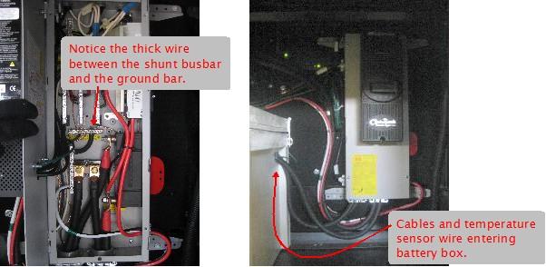
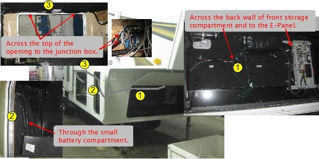
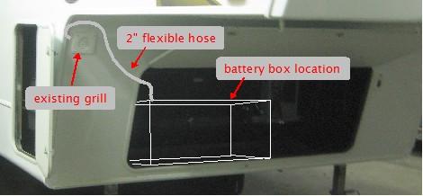
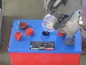
Unfortunately I don't have a good enough photo but the cover for the battery box that the customer made had a hole in the front left corner for venting (see photo below.) Batteries that are being used to power loads or are being charged produce hydrogen, the heavier the use the more the hydrogen. This hydrogen must not be allow to accumulate otherwise a spark might set it off, causing an explosion. A 2 inch flexible hose was run from the hole in the battery box cover, through the wall between this compartment and the adjacent small battery compartment, to an existing grill (see photo below.)
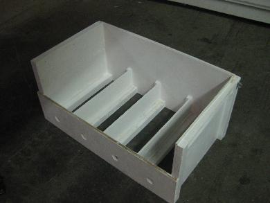
The four holes in the bottom front of the battery box are necessary to allow fresh air in (see photos above.) At the same time as the batteries are generating hydrogen, they also generate heat, heating the air in the battery box. Since hot air rises it will rise into of the vent hose in the top of the cover, pulling fresh air in from the four holes in the bottom front.
In one of the above photos you can see the cables and temperature sensor wire entering the battery box on the side near its top. Since I didn't want hydrogen coming out of here I sealed the gaps in this hole with silicon caulking.
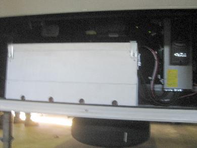
The box was wedged into the storage compartment snuggly with angle iron at its base. From the above photo on the left you can see spacers that keep that batteries from moving around much, though they are not perfectly snug. Air does have to be able to circulate around the individual batteries to prevent them heating up too much.
Battery maintenance
|
|
|
|
