This is how I made the drive system for version 2 of my
BB-8.
It's commonly called the hamster because it works like a hamster
running in a hamster ball to make the hamster ball rotate.
As previously stated, one of the goals for version 2 of my BB-8 was
to make a more powerful drive system so that I could have more
weight in the bottom of the ball. That was done by using drill
motors from cordless drills and drill batteries. That also gave me
the needed weight. To make turning work well, it's also a tank
drive, or differential drive. That means that to turn, the two motors
rotate in opposite directions.
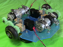
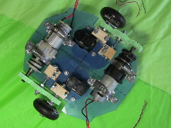
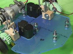
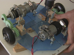
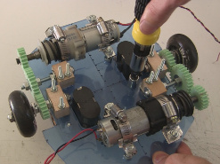
BB-8 drive system.
BB-8 drive system - top view.
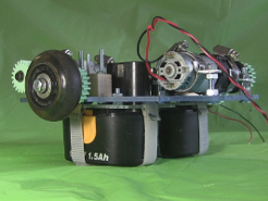
BB-8 drive system - side view.
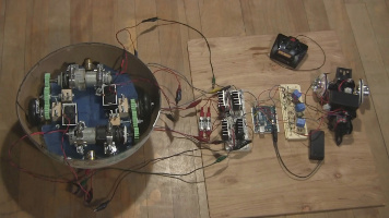
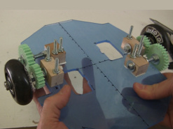
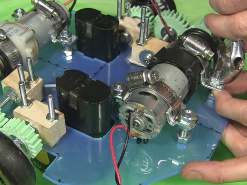
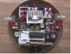
In the photo below is the drive system in the bottom half of the ball
for testing while I was finallizing the circuit. Note that the rollers
are attached to the two ends of the drive plate below but weren't
attached yet at the time the above photos were taken. (They're the
small brass colored objects at the uppermost end and lowermost end,
just touching the inside of the ball.) There's more about the rollers
at the bottom of this page.
Motors in the ball during testing.
The following video is part 1 in a series on making this BB-8 droid and
though it includes putting together the drive system as shown on this
page.
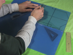
The drive plate
The drive plate is a piece of 1/4" thick acrylic (or possibly Lexan, a
polycarbonate plastic) that I cut out using my scroll saw.
Marking the plate.
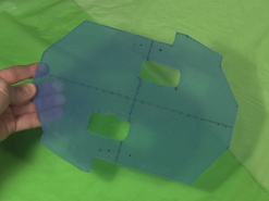
Cutting the plate.
The finished plate.
The wheel and gear assemblies
Three gears were needed to go from each motor shaft to the wheels
since the motors were on the sides and the wheels in the middle
as you can see from the photos at the top of this page. For each
motor/wheel the same sized small gear is at the motor shaft and
the wheel and then a bigger gear is between the two. I designed these
gears in Blender (3D modelling software) and 3D printed them. The
STL files are available below. Note that for some unknown reason I had to
drill out the center holes to 1/4" as they came out smaller.
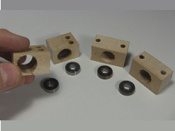
The first mechanical components I made were the wheel assemblies
with their gears and bearings. You can see the bearings in the photo
below. They were bought from a local bearing supply store such that they
were small and had a 1/4" inner diameter so that I could use 1/4"
bolts and threaded rods as the axels. I also needed somewhere to
house the bearings, holding them in place. For that I cut the
small blocks of hardwood to make bearing housings, also shown below.
I used a spade drill bit to make the big hole.
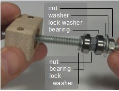
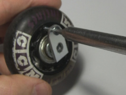
As shown below, I wanted two bearings per axle. Basically the recipe
was a nut, a washer, a small lock washer, a bearing, a nut
to act as an internal spacer, another bearing, another small lock washer,
another washer, and another nut. The two outer nuts sandwiched together
tightly on the ends. The bearings, lock washers and center nut were fit inside
the hole while the washers were larger than the hole and acted as endcaps
to keep the other parts in the hole. But, even though the whole thing was
compressed tightly together, the washers did not press hard
against the wood. Instead the washers touch the wood lightly and the
whole thing rotates easly while the wood stays in place.
Bearings and bearing housings.
Recipe for inside the bearing housing.
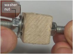
Final nut and washer.
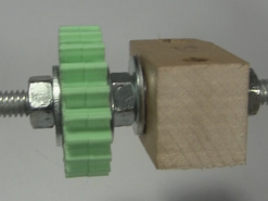
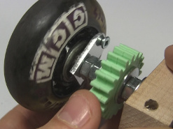
Next, as shown below, the gear was tightened to the axle with washers
and nuts on either side.
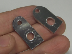
The same could not easily be done with rollerblade wheels though.
If the rollerblade wheel was tightened to the axle, the inner
part of the wheel would stay with the axle but the outer tire of
the wheel would spin freely on its bearing. To fix the tire part
firmly to the axle and have it turn only when the axle turned,
I made what I called wheel locks using some aluminum bar that I'd cut
and drilled into the shapes shown below. A screw was then put through
one of the holes in the wheel lock and screwed into a part of the
tire that conveniently already had a hole. Once fully assembled, this
would fix the tire relative to the lock and the axle.
The gear with washers and nuts.
The wheel locks.
Screwing the wheel lock to the wheel.
As shown below, then the axle was put through the other hole in the
lock and then nuts tightened against this and the wheel on both sides.
The tire part of the wheel now rotated only with the axle.
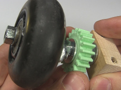
Also shown below, two more assemblies were done in very similiar
fashion except with a larger diameter gear and no wheel. This was
all installed on the drive plate.
Note that a lot of time and patience was taken to make sure the
bearings and parts in the housing all turned as easily as possible,
mostly making sure that the washers didn't press on the bearing housing,
restricting the rotation. The power from the motors had to be translated
from the motor, through the gears and bearings, to the wheel. Any
losses at any step along the way reduces the final torque at the wheel,
and I wanted all the torque I could get.
The wheel locked in place.
The other side of the wheel.
All wheel and gear assemblies.
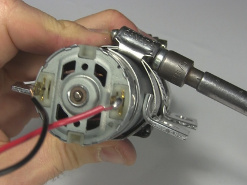
Mounting the drill motors
I needed some drill motors and
this page explains how to get drill motors from cordless drill.
I also needed a way to mount the drill motors that was strong but that
did not take up a lot of room on the drive plate since I still had
other things to keep room for. I settled on making some metal
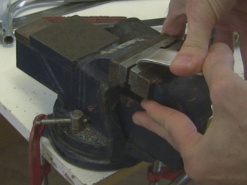
brackets using 1/8" thick aluminum bar from Home Depot. As shown
below, I put the bar in my vice and made a 90 degree bend in it.
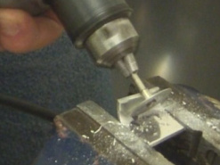
After cutting it and drilling a hole, I also put a Dremel cutting tool
on my power drill and cut a slot in the elbow of the bracket.
Bending some aluminum bar.
Cutting a slot.
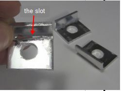
Finished motor brackets.
As shown below, the slot in each bracket was for putting the bracket
on a hose clamp for attaching to the motor. For each motor, three bolts
were then added to the drive plate and the motor was lowered onto
these. After making sure the gear on the motor shaft meshed and
transfered power efficiently to the wheel, the bolts were tightened.
Attaching the brackets using hose clamps.
Bolts in the drive plate.
Bolting a motor in place.
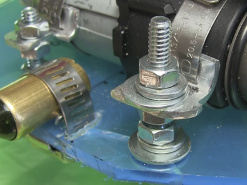
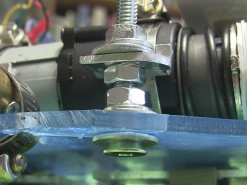
I later found that using just nuts wasn't enough to keep the motors from
moving under the stress and causing the gears to slip. As shown below,
I went back and added washers and lock washers.
Added lock washers and washers.
Lock washers and washers - bottom view.
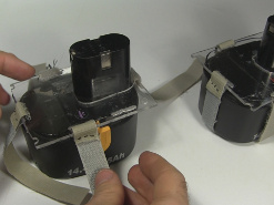
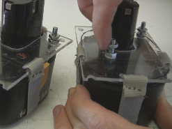
Attaching the drill batteries
The drill batteries are for powering the drill motors of course, but
they're also mounted as low as possible to act as heavy weights for
contributing to the stability of the BB-8 droid. As shown below,
to attach them to the drive plate I started by cutting up some acrylic
pieces and sewing velcro strips to the pieces. I then used the velcro
to strap the acrylic peices to the tops of the batteries.
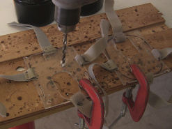
I next drilled holes in the drive plates for bolting the batteries on.
I then drilled matching holes in the battery's plates.
Battery plates with velcro strips.
Drilling holes in the drive plate.
Drilling holes in the battery plates.
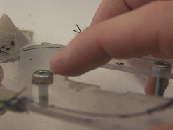
To make sure there wasn't unneccessary room taken up by the heads of the
bolts, as shown below, I countersunk the bolt heads in the acrylic.
I then added more nuts to the bolts so I could adjust the spacing
between the drive plates and these battery plates if needed.
Finally, I pushed those bolts up through the holes I'd made in the
drive plate and used nuts to fix them in place.
Countersunk holes.
Adding nuts to the bolts.
Bolting the batteries in place.
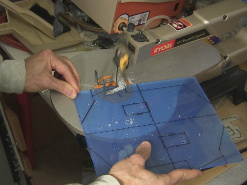
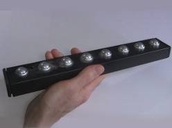
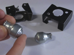
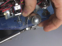
Rollers for the drive plate
As shown in first the photo below, two rollers were added to the ends of
the drive plate. The rollers were taken from the bar shown below that had
a bunch of rollers mounted in it. I found this bar in a local hardware
store and have no idea what its original purpose was. I removed two
rollers from this bar.
If you can't find a bar of rollers like this then you can make your
own rollers from a brass tube from a hobby store and marbles as I
show how to for
my BB-8 version 1.
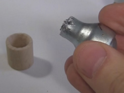
Notice that the rollers each have a narrow stem.
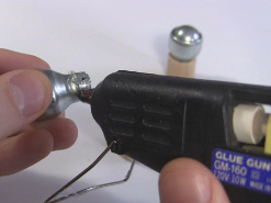
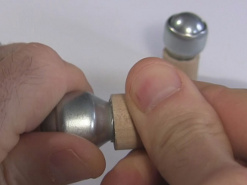
I drilled holes in two pieces of dowel for this stem to fit into and
hot glued them into the dowels. Ideally the dowel should have a diameter
that is the same or larger than the larger diameter part of the rollers.
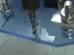
To mount the roller on the plate, two slots were cut out of the plate
at either end by melting the plate using an old soldering iron. Then a hose
clamp was pushed through the slots and tightened around the roller,
holding the roller firmly in place. By loosening the hose clamp it's
easy to move the roller in and out to adjust its distance to the ball.