BB-8 (v2) drive electronics
This is how I did the electronics for version 2 of my BB-8 droid.
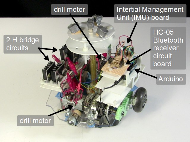
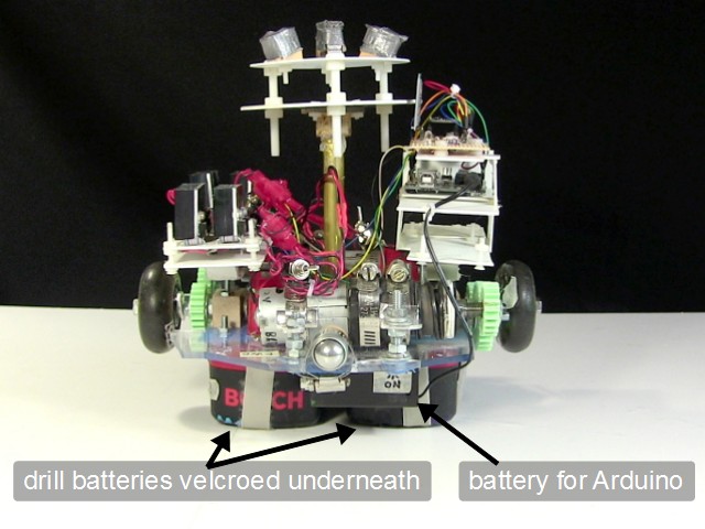
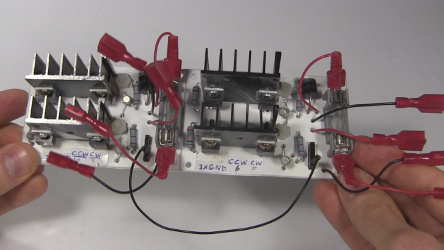
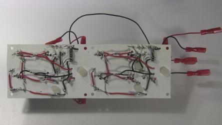
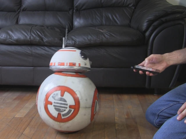
The photos above are of the drive system that that goes inside the ball. It works the same way that the Sphero BB-8 droid toy works. The schematic is also below. To make the ball rotate I'm using two motors salvaged from old cordless drills. Each drill is powered by its own drill battery and its own H bridge circuit. To tell them to move I'm using an app I wrote for my Android phone that has buttons to tell it to move backward, foreword, spin on the spot, ... The app then uses Bluetooth to communicate with an HC-05 receiver board that passes those commands on to an Arduino. The Arduino then takes that and outputs to some transistors that then controls an H bridge circuit for each motor. The speed is controlled by having the Arduino pulse those transistors using Pulse Width Modulation (PWM).
The Intertial Management Unit (IMU) is the BNO055 and is used to control the motors in such a way as to counter the wobble. However, at this time it is not being used.
The following video is part 1 in a series on making this BB-8 droid and though it doesn't go through wiring up the electronics step-by-step, it does show them at different stages and mounting them in the BB-8. Note that some of it has changed since the video was made. Relevant here is that the remote control taken from a toy truck has been replaced with the Android app communicating with an HC-05 board.
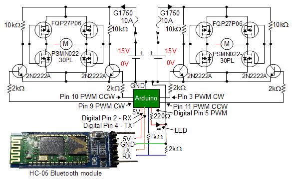
BB-8 (v2) drive system schematic
Below is the schematic for the drive system. The section drawn below the Arduino is for communicating with the HC-05 board to get commands from the Andriod phone. The section above the Arduino is two H bridge circuits for controlling the two motors. You can buy single or dual H bridge boards already made, however, since I needed somewhere between 5 amps and 10 amps for my motors, commercially made H bridge boards for that current was above my budget so I made the circuits shown from scratch instead. But now that I know what my electrical current requirements are, I've found some dual H-bridge boards that are affordable and if I didn't value the learning experience in making my own, I would have bought a dual H-bridge/motor driver board instead instead. Here are some affordable dual H-bridge/motor driver boards which you can buy online:
- 10A 5-25V Dual Channel DC Motor Driver for brushed motors, product code RB-Cyt-153 on robotshop.com
- Pololu Dual VNH5019 Motor Driver Shield for Arduino, 5.5 to 24 V and can deliver a continuous 12 A (30 A peak) per motor, or a continuous 24 A (60 A peak) to a single motor
Here is the parts list for the dual H-bridge board:
- resistors: 4 x 10kΏ, 4 x 2kΏ
- MOSFETs: 2 x FQP27P06, 2 x PSMN02230PL
- NPN transistors: 4 x 2N2222A
- diodes: 2 x G1750 (equivalent to the NTE5812)
- switches: 2 that are rated at least 17V DC and 10A
- fuses: 2 x 10A fuses (1/4" x 1 1/4") glass tube type
- fuse holders: 2 (I cut mine from a fuse block that had two attached to each other)
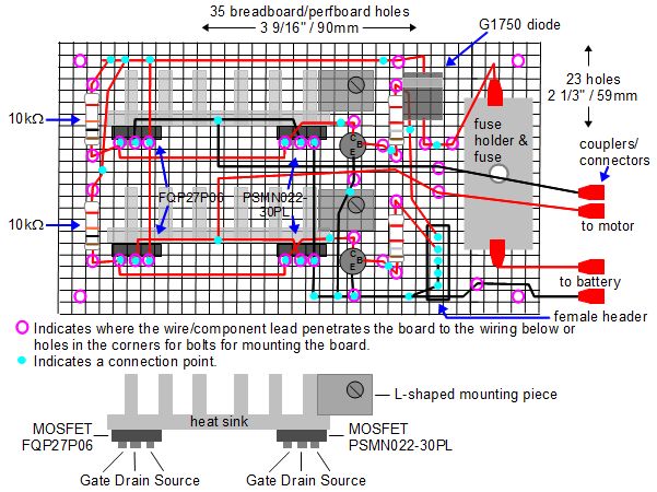
- heat sinks for mounting the MOSFETs on to (see the photos for what size worked for me, mine were cut from a larger piece)
- female headers (pin headers): to plug wires into the board from the Arduino I put on some female headers with 5 holes. You can buy a pack of 5 36-pin 0.1" female headers from adafruit.com. You can see them labeled in the perfboard diagram below and in the video above.
- couplers/connectors: to plug into the motors, battery and fuse holder I used couplers. You can see them labeled in the perfboard diagram below and in the video above.
Parts can be found in electronics stores, automotive stores, online, and recycled from electronics that is being thrown out as garbage. If you can't find the same part numbers as mine then look for what are called equivalent parts.
For mounting it, I put it on a piece of plastic but I first put it on a breadboard and worked out that a single H-bridge would fit on a perf board (a board with pre-made holes in it) as shown in the following diagram. For the dual H-bridge I simply put two of these side-by-side. Note that if your parts are different sizes than mine or your perf board holes are spaced apart a different amount then the dimensions in the diagram below may not help you.
See below for more about H-bridge boards and the RC receiver to Arduino converter circuit.
BB-8 (v2) Arduino code/sketch
The following code simply turns the motors on and off when the remote control tells it to. There is no acceleration control, stabilization, or anything else.
/* BB-8 (v2) Arduino code May 22, 2017 - First version using the HC-05 Bluetooth tranceiver board as the remote control receiver and a mobile phone with a custom app as the remote control transmiter. Full details about this BB-8 droid can be found at: http://rimstar.org/science_electronics_projects/bb-8_star_wars_droid_v2.htm Drive motor circuits -------------------- The two motors are driven independently as what's called a tank or differential drive. Each one can turn in two directions. Since it's a tank/differential drive, to go forward one motor must turn clockwise while the other motor turns counterclockwise. That makes the wheels both turn in the same direction when viewed from above. To make is spin around on the spot while remaining stationary, both motors must turn clockwise to spin in one direction or counterclockwise to spin in the opposite direction. That makes the wheels turn in opposite directions when viewed from above. Just which direction is called foward and which is reverse is chosen arbitratily since the BB-8 doesn't really have a forward or reverse direction (there's a piece of tape with "FWD" on one end of the drive plate to indicate the arbitrarly selected forward end). For this implementation, the remote control is done using an Android phone with a DIY Android app. It uses Bluetooth to communicate with an HC-05 Bluetooth tranceiver board which is wired up to the Arduino. The HC-05 communicates with the Arduino over those wires using the software serial library. That keeps the hardware serial available for debugging purposes if needed. The HC05_CMD_* values below are the one byte data that the Android app sends to the HC-05 and that the Arduino processes. Also, for this implementation, an LED is turned on while the motors are running and off when the motor is stopped. If the motors aren't turning when they're supposed to but the LED is on then this indicates that the problem isn't with the communication. Of it the LED is off when it's supposed to be on, then this indicates that the problem is with the communication. The two motors are then controlled using two H bridge circuits. With the DIY H bridge circuits for this implementation, controlling each H bridge circuit is done by the Arduino by turning on and off transistors using digital pins. There are two transistors for each H bridge, one for each direction the motor can turn. The motors each can turn counter clockwise (CCW) or clockwise (CW) depending on which transistor is turned on. Pulse Width Modulation (PWM) is done to these pins for speed control. The variables bridge1PWMduty, for motor 1, and bridge2PWMduty, for motor 2, have the PWM values. 0 turns the transistor/motor off. The pins are: bridge1CWPin - digital pin for motor 1 clockwise bridge1CCWPin - digital pin for motor 1 counter clockwise bridge2CWPin - digital pin for motor 2 clockwise bridge2CCWPin - digital pin for motor 2 counter clockwise */ #include// We're using software serieal because we're saving the digital pins 0 (RX) and 1 (TX) // for the serial console for debugging. They're common with the USB serial. #define HC05_TX 2 // this is digital pin for the HC-05's TX pin, on the Arduino side it's RX #define HC05_RX 4 // this is digital pin for the HC-05's RX pin, on the Arduino side it's TX SoftwareSerial hc05_serial = SoftwareSerial(HC05_TX, HC05_RX); // HC05_CMD_* are the commands that the mobile phone app transmits. It sends 1 byte messages, // containing the values below. Make sure the values match what the app transmits. #define HC05_CMD_FORWARD 1 #define HC05_CMD_BACKWARD 2 #define HC05_CMD_SPINCCW 3 #define HC05_CMD_SPINCW 4 #define HC05_CMD_STOP 5 #define HC05_CMD_FORWARDLEFT 6 #define HC05_CMD_FORWARDRIGHT 7 #define HC05_CMD_BACKWARDLEFT 8 #define HC05_CMD_BACKWARDRIGHT 9 int hc05_debugLEDPin = 5; // used to turn on and off an LED for diagnostic purposes // Stuff for what's considered the left wheel and the motor mounted on the front. int bridge1CWPin = 9; // digital pin 9 for PWM int bridge1CCWPin = 10; // digital pin 10 for PWM int bridge1PWMduty = 56; // duty cycle for H bridge 1 // (a value of 25 blew a 1 amp fuse and // 48 blew a 3 amp fuse but not a 5 amp fuse.) // Stuff for what's considered the right wheel and the motor mounted on the back. int bridge2CWPin = 3; // digital pin 3 for PWM int bridge2CCWPin = 11; // digital pin 11 for PWM int bridge2PWMduty = 44; // duty cycle for H bridge 2 // (a value of 12 blew a 1 amp fuse and // 48 blew a 3 amp fuse but not a 5 amp fuse.) void turnMotor1Off() { analogWrite(bridge1CWPin, 0); // off analogWrite(bridge1CCWPin, 0); // off } void turnMotor1CW() { analogWrite(bridge1CWPin, bridge1PWMduty); // PWM duty cycle analogWrite(bridge1CCWPin, 0); // off } void turnMotor1CCW() { analogWrite(bridge1CWPin, 0); // off analogWrite(bridge1CCWPin, bridge1PWMduty); // PWM duty cycle } void turnMotor2Off() { analogWrite(bridge2CWPin, 0); // off analogWrite(bridge2CCWPin, 0); // off } void turnMotor2CW() { analogWrite(bridge2CWPin, bridge2PWMduty); // PWM duty cycle analogWrite(bridge2CCWPin, 0); // off } void turnMotor2CCW() { analogWrite(bridge2CWPin, 0); // off analogWrite(bridge2CCWPin, bridge2PWMduty); // PWM duty cycle } void setup() { pinMode(bridge1CWPin, OUTPUT); pinMode(bridge1CCWPin, OUTPUT); pinMode(bridge2CWPin, OUTPUT); pinMode(bridge2CCWPin, OUTPUT); turnMotor1Off(); turnMotor2Off(); pinMode(hc05_debugLEDPin, OUTPUT); hc05_serial.begin(9600); // default baud rate for the Bluetooth module //Serial.begin(9600); // for sending debugging messages to the Arduino IDE's Serial Monitor } void loop() { int hc05_data; if (hc05_serial.available() > 0) { // did we receive a command from the remote control? hc05_data = hc05_serial.read(); // get the command //Serial.print("hc05_data: "); // write debugging data to the Arduino IDE's Serial Monitor //Serial.println(hc05_data); switch (hc05_data) { case HC05_CMD_FORWARD: //hc05_serial.println("Forward"); <= sending back to the mobile phone app, not implemented analogWrite(hc05_debugLEDPin, 20); turnMotor1CCW(); turnMotor2CW(); break; case HC05_CMD_BACKWARD: analogWrite(hc05_debugLEDPin, 20); turnMotor1CW(); turnMotor2CCW(); break; case HC05_CMD_SPINCCW: analogWrite(hc05_debugLEDPin, 20); turnMotor1CW(); turnMotor2CW(); break; case HC05_CMD_SPINCW: analogWrite(hc05_debugLEDPin, 20); turnMotor1CCW(); turnMotor2CCW(); break; case HC05_CMD_STOP: analogWrite(hc05_debugLEDPin, 0); turnMotor1Off(); turnMotor2Off(); break; case HC05_CMD_FORWARDLEFT: analogWrite(hc05_debugLEDPin, 20); turnMotor1Off(); turnMotor2CW(); break; case HC05_CMD_FORWARDRIGHT: analogWrite(hc05_debugLEDPin, 20); turnMotor1CCW(); turnMotor2Off(); break; case HC05_CMD_BACKWARDLEFT: analogWrite(hc05_debugLEDPin, 20); turnMotor1Off(); turnMotor2CCW(); break; case HC05_CMD_BACKWARDRIGHT: analogWrite(hc05_debugLEDPin, 20); turnMotor1CW(); turnMotor2Off(); break; } } }
The H bridge circuit
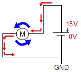
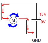
The motors are DC motors and some way is needed to make them rotate in one direction or the other direction. As shown below, that can be done manually by connecting a DC motor to the battery one way, which in our example makes the motor rotate counterclockwise. Then, to make it rotate clockwise the connections to the battery are manually reversed.
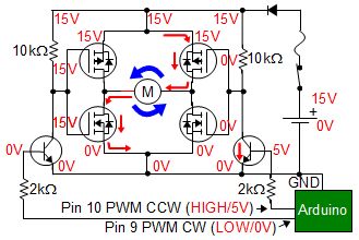
An H bridge is a circuit that does the same thing electronically. The two NPN transistors in the circuit below are the key to selecting the motor direction using the Arduino.
In the diagram on the left below, the Arduino sets pin 10 HIGH, which means the Arduino applies 5 volts to the pin. That turns on the NPN transistor that's connected to that pin, which then lowers that side of the H bridge to 0V. That causes the lower N-type MOSFET on that side to be off. It also causes the causes the upper P-type MOSFET to be on, resulting in current to be able to flow through that upper MOSFET. For the MOSFETs on the left in that diagram, nothing's changed, and that means the voltages are such that top MOSFET is off and the bottom MOSFET is on. That all causes current to flow through the motor in the direction that makes it turn counterclockwise (for example.)
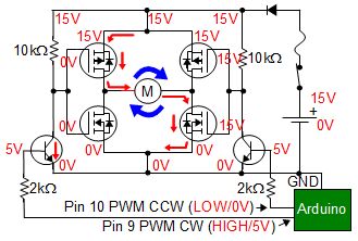
In the diagram on the right below, the Arduino instead sets pin 9 HIGH, which causes the same to happen to the other side of the H bridge instead. From there what happens is just a mirror of what's described in the paragraph above. Since current flows through the motor in the opposite direction, the motor this time turns clockwise.
I found this way of using NPN transistors to interface with the Arduino on Lewis Loflin's webpage.
I don't know exactly what the maximum normal current can be through the fuse and diode but I blew 5A fuses and the next highest rated fuse I had was a 10A fuse. As far as I can tell, the G1750 diode is rated for 6A, though it may be higher since all I had to go on was an equivalent diode's datasheet ( NTE5812).
Below are views of the completed 2 H bridges on a single board, commonly referred to as a dual H bridge board. The red connectors are for connecting to the batteries and the motors. For the board itself I used a piece of plastic which I'd long ago bought from a hobby store because I didn't have enough perfboard at the time, and it works just as well.
I have found that running the BB-8 for a few minutes does cause the heat sinks that the MOSFETs are mounted on to heat up, so they are necessary.
The remote control using an Android app and Bluetooth
The remote control receiver to Arduino converter circuit - old way

