I needed some way to remotely control my
BB-8 droid at a very low cost
and I also wanted to use an Arduino to do speed control
using Pulse Width Modulation (PWM). So I bought a remote control
toy truck at a yard sale and hacked together a circuit to convert
the remote control's output to something the Arduino would understand.
Note that I later removed this and replaced it with a far more compact,
flexible and longer communication distance method using
an HC-05 board that allows me to control the BB-8 from my phone
over Bluetooth.
RC receiver to Arduino converter circuit.
 |
|
|
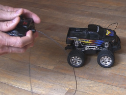
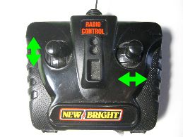
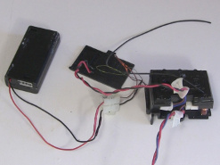
RC toy truck and controller.
 |
|
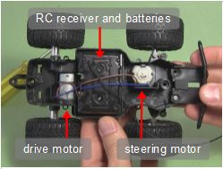
Top of truck removed.
 |
|
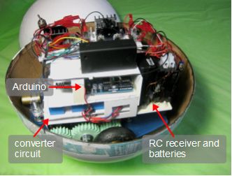
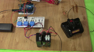
As shown above, the central part of the truck was an RC receiver and
batteries. Two wires came out of that to go the the drive motor and
two more wires came out to go to the steering motor.
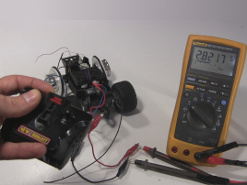
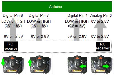
From testing shown below, both sets of wires produced the same outputs when
being controlled. When a stick on the remote
control was pushed up or to the right, depending on which stick,
a set of RC receiver wires put out a positive voltage, around 2.8 volts.
When a stick on the remote control was pushed down or to the left,
a set of RC receiver wires put out a negative voltage, around -2.8 volts.
Note that the voltages were either fully 2.8 or -2.8 volts, or 0 volts.
There was no gradual change. It was either on or off, meaning I wouldn't
be able to control motor speed using the remote controller, only
rotate the motors in either direction or turn them off.
They're basically on/off switches.
Remote control sticks: drive and steer
 |
|
Testing RC receiver output.
 |
|
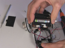
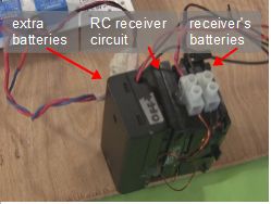
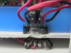
I didn't need the whole toy truck or its motors so, as shown below,
it was a simple matter of removing one screw and then using some gentle
pressure to snap the central part from the toy truck out, that being
the RC receiver and the battery case attached to it. The batteries were
2 AA batteries connected in series. But to get a longer battery life
I hot glued on a second battery case, also with 2 AA batteries in series,
and then paralleled that set with the first set.
Removing RC receiver from truck.
 |
|
Extra batteries case and RC receiver.
 |
|
Extra batteries case and RC receiver.
 |
|
Next came figuring out a circuit to convert the 2.8V and -2.8V from the
RC receiver to things that the Arduino could understand. The following
is the high-level diagram of what ended up being done. Notice that in
some cases the 2.8V and -2.8V were converted to 5V except one case
where the 2.8V was given to the Arduino unchanged. The sections
below explain the circuit in detail.
RC receiver to Arduino high-level diagram.
 |
|
Handling the 2.8V from the RC receiver
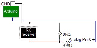
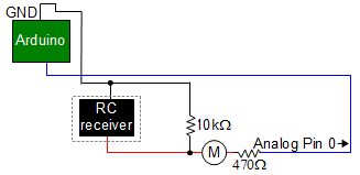
Handling the 2.8V was easy. The Arduino has analog input pins that accept
from 0V to 5V. The Arduino the converts that to a number from
0 to 1023 (0 for 0V and 1023 for 5V) which your Arduino program can get
using the AnalogRead() function. Here's the part of the circuit for
handling the 2.8V. But be careful. Those analog input pins can handle at
most 20mA of DC current. Below is part of the circuit for handling the
2.8V only.
Simple analog input.
 |
|
Why the 470 ohm resistor? As I said above, the Arduino's analog input
pins can
handle at most 20mA of current. One way of limiting the current is
to run it through a resistor, and waste some of the energy as heat,
reducing the current that way. To know what size resistor to use I first
made sure I had new batteries in the RC receiver side of things.
I put a meter in series for measuring the current, as shown below,
and tried different sized resistors, starting with very large values.
Starting with large values resulted in current much lower than 20mA.
I tried lower and lower value resistors until I got something close to
20mA, but still less than 20mA. I settled on 470 ohms.
Position of the meter.
 |
|
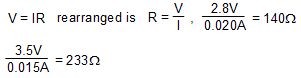
Instead of trying a bunch of different valued resistors, you can use
a potentiometer (variable resistor), provided you have one in a
suitable range. You can also get close by doing a simple calculation.
As shown below, ohms law states that V = IR, voltage equals the
current multiplied by the resistance. Rearranging to solve for the
resistance we get R = V/I, resistance equals the voltage divided by
the current. So 2.8V divided by 20mA gives a resistance of 140 ohms.
But suspecting that the maximum voltage might be higher than 2.8V and
wanting to keep the current safely below 20mA by a bit, you might
instead calculate 3.5V/15mA = 233 ohms.
Ohm's law calculations for current limiting resisance.
 |
|
Why did I put a 10 kilohm resistor connected to ground in the above
circuit? That was so that when the RC receiver is off, any stray current
will go through the 10 kilohm resistor to ground instead of causing false
readings at the Arduino. This is called a pull-down resistor. I'm not sure
it's needed in this case. What effect does it have when the RC receiver
is on though? Since it's such a high resistance value, very little current
will go through it normally. The value, 10 kilohm, is a typical value
for this use.
Handling the -2.8V from the RC receiver
Handling the -2.8V was harder. That's because the Arduino doesn't
accept negative voltage for anything on any of it's input pins.
So I either had to turn the -2.8V into 2.8V or cause the -2.8V to
result in something else. I chose to do the latter.
If you give the Arduino 5V on one of its digital pins then if
you do a DigitalRead(Pin) then it will return HIGH. If the same pin
has 0V on it then it will return LOW. Luckily the Arduino has
a 5V source you can use for this purpose.
So I needed some way for -2.8V from the RC receiver to result in
one of the Arduino's digital pins getting 5V from the Arduino's own
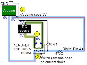
5V source. One easy way to do that it using a relay, as shown below.
Relay not energized.
 |
|
Relay energized with -2.8V.
 |
|
In the first schematic above, this is what happens when there is 0V
from the RC receiver (see voltages shown in blue lettering.) The relay's
coil is not energized. You can tell this by looking at the switch in the
bottom part of the relay. The switch is open, meaning that no current
will flow through the path highlighted in blue. As a result, the Arduino
will see
0V at the pin that the circuit is connected to, digital pin 4 in this
case. This causes a call to DigitalRead(4) to return the value LOW, which
in this case means the remote control has not been activated and either
nothing should be done or something that was going on should be stopped.
With my BB-8 this indicates that a motor should be stopped.
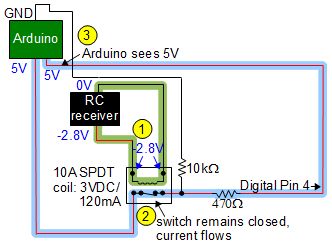
But in the second schematic above, the relay is energized. The RC
receiver has put either 2.8V or -2.8V across the relay's coil,
it doesn't matter which. That closes the switch, connecting the two
parts highlighted in blue on either side of the switch.
The Arduino will now see 5V at digital pin 4.
This causes a call to DigitalRead(4) to return the value HIGH, which
in this case means the remote control has been activated and something
should be done. With my BB-8 this indicates that a motor should start
turning.
The 10 kilohm resistor is again there as a pull-down resistor. After
the relay's switch opens there may still be some stray noise on the
wire going to the Arduino's pin and voltage won't be 0V at the pin
as it should be.
With the 10 kilohm resistor, stray current will have a path
through the resistor to ground, pulling the voltage firmly down to
0V. But what about when the switch is closed? When the switch is closed
the 10 kilohms of resistance is so much higher than the practically
0 ohm resistance through the wire going to the Arduino's pin that
relatively no current will go through the 10 kilohm resistor path.
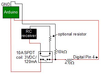
In the circuit below you can also see an optional resistor. You may
want to put one there in order to limit the current through the
relay's coil and, just as importantly, through the Arduino.
In my case I tried resistances here all the way down to
4.7ohms, but the current wouldn't close the relay with even that
resistance. Once I went to 0ohms here, i.e. no resistor, the relay closed.
The current was 70mA when it finally closed.
Optional resistor.
 |
|
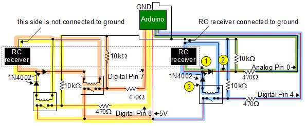
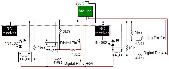
The complete circuit
Below is the complete circuit. Note the one simple sub-circuit highlighted
in green for taking 2.8V from the RC receiver and giving analog input to
the Arduino, as talked about above. Then note the three relay
sub-circuits highlighted in the other colors for taking either
2.8V or -2.8V and giving 5V to the Arduino, also as talked about above.
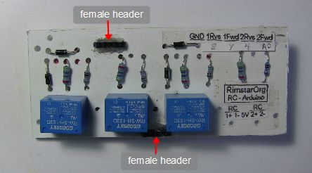
Here is the parts list for the RC receiver to Arduino converter board:
- resistors: 4 x 10kΏ, 4 x 470Ώ
- diodes: 4 x 1N4002
- relays: 3 x 10A SPDT, coil: 3VDC/120MA
- female headers (pin headers): to plug wires into the board from
the RC receiver and to go to
the Arduino I put on some female headers. You can
buy a pack of 5 36-pin 0.1" female headers from
adafruit.com. You can see them labeled in a photo below
and a closeup in another photo below that.
Parts can be found in electronics stores, automotive stores, online,
and recycled from electronics that is being thrown out as garbage.
If you can't find the same part numbers as mine then look for
what are called equivalent parts.
The diodes - choosing which sub-circuits to use
Other things to note are the use of the 1N4002 diodes. As pointed out
near the top of this page, the RC receiver has two sets of wires
for output, one set for the driving motor and one set for the steering
motor. In the schematic below you can see the two sides, each with
two sub-circuits. On the left there are two relay sub-circuits (yellow
and orange) and on the right there is one relay sub-circuit (blue)
and a simple analog sub-circuit (green).
But something has to choose which sub-circuit to use on either side.
On the right side, when the bottom of the RC receiver is 2.8V there
will be 2.8V on the side of the diodes indicated by the number 1.
The sides of the diodes indicated by the 2 and 3 will be 0V. Notice that
the diodes are oriented in opposite ways. The one on the green path
is pointing away from the number 1 side and the one on the blue path
is pointing toward the number 1 side. If the number 1 side is at 2.8V
with respect to the number 2 then current will flow through that diode
on the green path. That's because current flows through a diode when
the diode is pointing at the side that's more negative (0V is more
negative than 2.8V). It flows from the positive to the negative (this
is conventional current, not electron flow current.)
But when the number 1 side is -2.8V, current will flow through
the diode on the blue path. That's because that diode will now be point
toward the side that's more negative (-2.8V is more negative than 0V.)
And that's how the diodes select which sub-circuit will be used.
Notice that the left side of the RC receiver also has two diodes
which operate in the same way.
Grounding problem
Why are there that mix of sub-circuits? The relay sub-circuits were
originally there because I needed a way to turn -2.8V into something
the Arduino can understand. But on the left side you can see that
I'm using a relay sub-circuit for handling 2.8V as well. Why didn't
I just use a simple analog sub-circuit as I did on the right side?
In fact, I did do just that originally. But that meant that both
sides of the RC receiver were connected to ground. In the above
diagram I've indicated the one place where there's a ground
connection going into the receiver, on the right side of the RC
receiver, and that there isn't a ground connection on the
left side. Having both sides connected to ground meant that those
two points of the RC receiver were connected together and that
caused weird outputs from the RC receiver overall.
Connecting those two points must
have interfered with whatever was going on in the circuit inside
the RC receiver itself.
So to avoid having a ground connection from the RC receiver on
the left side, I handled the positive 2.8V with another relay sub-circuit.
On the right side, the simple analog sub-circuit needs the connection
to the Arduino's ground because analog pin 1 expects the 2.8V voltage
to be relative to the Arduino's ground.
Lastly, you might ask why I didn't just use a relay sub-circuit instead
of the simple analog sub-circuit and have no ground connection to
the RC receiver. The reason is that I wanted to save
on the cost of a 4th relay.
The complete circuit
The complete circuit.
 |
|
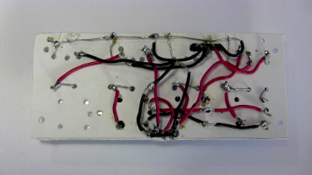
The follow is the resulting circuit board. Note that I didn't have enough
perf board so I drilled holes in some plastic and used that instead.
The back view below is the reverse left-to-right of the front view
since that's what happens when you flip it over to see the back.
I also drilled extra holes on the right side in case I ever want
to change the simple analog sub-circuit to also be a relay sub-circuit
instead (plus there are extra holes that turned out to be not needed.)
Front.
 |
|
Back.
 |
|
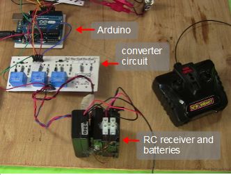
In the photo below the circuit is connected to the RC receiver on the
bottom and the Arduino on top. This was during the final testing of the
circuit before putting it in the BB-8. Note the use of female pin headers
for connecting to the rest of the circuit.
The circuit connected up.
 |
|
Female pin header.
 |
|
BB-8 (v2) Arduino code/sketch
The following code simply turns the motors on and off when the remote
control tells it to. There is no acceleration control, stabilization,
or anything else.
/*
BB-8 (v2) Arduino code

July 6, 2016 - Switched pins 5 and 6 to 3 and 11 to use the
lower PWM frequency (Arduino UNO). This is because I'm using
brushed motors, and unlike with brushless motors, the higher
the frequency, the worse it is for brushed motors.

Full details about this BB-8 droid can be found at:
http://rimstar.org/science_electronics_projects/bb-8_star_wars_droid_v2.htm

Drive motor circuits
--------------------

The two motors are driven independently and so there are two
Radio Controls (RC), one for each motor. Each one can turn
in two directions. A circuit exists between the RC receiver
and the Arduino to give the Arduino the following inputs:
rc1FwdPin - a digital pin indicating that motor 1 should be
 turned on in the _forward_ direction (HIGH) or off (LOW)
rc1RvsPin - a digital pin indicating that motor 1 should be
 turned on in the _reverse_ direction (HIGH) or off (LOW)
rc2FwdPin - an analog pin indicating that motor 2 should be
 turned on in the _forward_ direction (value > 0) or off (0)
rc2RvsPin - a digital pin indicating that motor 2 should be
 turned on in the _reverse_ direction (HIGH) or off (LOW)
Note that one of the pins above is an anlog pin simply to
save on the cost of one more relay. The relays were needed
as using analog for all of them meant problems with common
ground in the RC receiver.

The two motors are then controlled using two H bridge circuits.
Controlling each H bridge circuit is done by the Arduino by
turning on and off transistors using digital pins. There
are two transistors for each H bridge, one for each direction
the motor can turn. The motors each can turn
counter clockwise (CCW) or clockwise (CW) depending on which
transistor is turned on. Just which direction is called foward
and which is reverse is chosen arbitratily since the BB-8
doesn't really have a forward or reverse direction.
Pulse Width Modulation (PWM) is done to these pins for speed
control. The variables bridge1PWMduty, for motor 1, and
bridge2PWMduty, for motor 2, have the PWM values. 0 turns
the transistor/motor off.
The pins are:
bridge1CWPin - digital pin for motor 1 clockwise
bridge1CCWPin - digital pin for motor 1 counter clockwise
bridge2CWPin - digital pin for motor 2 clockwise
bridge2CCWPin  - digital pin for motor 2 counter clockwise
Note that since it's a tank drive, to go forward one motor
must turn clockwise while the other motor turns counterclockwise.
*/

int bridge1CWPin = 9;    // digital pin 9 for PWM
int bridge1CCWPin = 10;  // digital pin 10 for PWM
int rc1FwdPin = 7;       // digital pin 7, relay's switch
int rc1RvsPin = 8;       // digital pin 8, relay's switch
int bridge1PWMduty = 48; // duty cycle for H bridge 1
                         // (a value of 25 blew a 1 amp fuse and
                         // 48 blew a 3 amp fuse but not a 5 amp fuse.)

int bridge2CWPin = 3;    // digital pin 3 for PWM
int bridge2CCWPin = 11;   // digital pin 11 for PWM
int rc2FwdPin = 0;       // analog pin 0
int rc2RvsPin = 4;       // digital pin 4, relay's switch
int bridge2PWMduty = 48; // duty cycle for H bridge 2
                         // (a value of 12 blew a 1 amp fuse and
                         // 48 blew a 3 amp fuse but not a 5 amp fuse.)

void turnMotor1Off()
{
  analogWrite(bridge1CWPin, 0); // off
  analogWrite(bridge1CCWPin, 0); // off
}
void turnMotor1CW()
{
  analogWrite(bridge1CWPin, bridge1PWMduty); // PWM duty cycle
  analogWrite(bridge1CCWPin, 0); // off
}
void turnMotor1CCW()
{
  analogWrite(bridge1CWPin, 0); // off
  analogWrite(bridge1CCWPin, bridge1PWMduty); // PWM duty cycle
}

void turnMotor2Off()
{
  analogWrite(bridge2CWPin, 0); // off
  analogWrite(bridge2CCWPin, 0); // off
}
void turnMotor2CW()
{
  analogWrite(bridge2CWPin, bridge2PWMduty); // PWM duty cycle
  analogWrite(bridge2CCWPin, 0); // off
}
void turnMotor2CCW()
{
  analogWrite(bridge2CWPin, 0); // off
  analogWrite(bridge2CCWPin, bridge2PWMduty); // PWM duty cycle
}

void setup()
{
  pinMode(bridge1CWPin, OUTPUT);
  pinMode(bridge1CCWPin, OUTPUT);
  pinMode(bridge2CWPin, OUTPUT);
  pinMode(bridge2CCWPin, OUTPUT);

  turnMotor1Off();
  turnMotor2Off();

  //Serial.begin(9600); // for sending debugging messages
}

boolean debounce(boolean last, int switchPin)
{
  boolean current = digitalRead(switchPin);
  if (last != current) {
    delay(5);
    current = digitalRead(switchPin);
  }
  return current;
}

int rc1FwdValPrev = LOW;
int rc1RvsValPrev = LOW;
int rc2FwdValPrev = 0;
int rc2RvsValPrev = LOW;

void loop()
{
  int rc1FwdVal = 0;
  int rc1RvsVal = 0;
  int rc2FwdVal = 0;
  int rc2RvsVal = 0;

  /*
   * Handle Motor 1
   */

  // get the relay's switch position
  rc1FwdVal = debounce(rc1FwdValPrev, rc1FwdPin);
  //Serial.print("1F:");
  //Serial.println(rc1FwdVal);
  if (rc1FwdValPrev != rc1FwdVal) {
    // the switch position changed
    rc1FwdValPrev = rc1FwdVal;
    if (rc1FwdVal == HIGH) {
      // the relay was turned on
      turnMotor1CCW();
    } else {
      // the relay was turned off
      turnMotor1Off();
    }
  }

  // get the relay's switch position
  rc1RvsVal = debounce(rc1RvsValPrev, rc1RvsPin);
  //Serial.print("1R:");
  //Serial.println(rc1RvsVal);
  if (rc1RvsValPrev != rc1RvsVal) {
    // the switch position changed
    rc1RvsValPrev = rc1RvsVal;
    if (rc1RvsVal == HIGH) {
      // the relay was turned on
      turnMotor1CW();
    } else {
      // the relay was turned off
      turnMotor1Off();
    }
  }

  /*
   * Handle Motor 2
   */

  rc2FwdVal = analogRead(rc2FwdPin);
  //Serial.print("2F:");
  //Serial.println(rc2FwdVal);
  if (rc2FwdVal > 0 && rc2FwdValPrev == 0) {
    turnMotor2CW();
    rc2FwdValPrev = rc2FwdVal;
  } else if (rc2FwdVal == 0 && rc2FwdValPrev > 0) {
    turnMotor2Off();
    rc2FwdValPrev = 0;
  }

  // get the relay's switch position
  rc2RvsVal = debounce(rc2RvsValPrev, rc2RvsPin);
  //Serial.print("2R:");
  //Serial.println(rc2RvsVal);
  if (rc2RvsValPrev != rc2RvsVal) {
    // the switch position changed
    rc2RvsValPrev = rc2RvsVal;
    if (rc2RvsVal == HIGH) {
      // the relay was turned on
      turnMotor2CCW();
    } else {
      // the relay was turned off
      turnMotor2Off();
    }
  }

  delay(50);
}
Alternatives to relays - using opto-isolators
A problem with relays is that they require the coil to be energized
for the entire time that the switch is to be closed (closed for a
normally-open relay, or open for a normally-closed relay.) An alternative
may be to use an opto-isolator in place of each relay. I haven't tried
it myself, and have never worked with opto-isolators so I don't know
how well it would work and what the limitations or issues would be.
But it's an alternative to explore.