Now that I have my new disks I could finally
start trying to test some of the ideas that were coming together re
how the testatikas might work and observations about how they're wired.
The basic idea being tested below is that:
- the output comes from the pots and the source may be ZPE tapped
at the middle grid cylinder(s)/mesh,
- the ZPE tapping is done by placing a HV DC electric field across
the middle grid cylinder(s)/mesh,
- other frequencies are placed on top of the HV DC to perturb the
electric field and hence the ZPF,
- this perturbing in the region of the grid perforations/mesh causes
the creation of charged particles from the ZPF along with some
momentum (i.e. energetic particles), and that
- a potential, whether DC or pulses, is required between the two
pot's outputs to cause the resulting energy to flow through a load.
Either that or something totally different will happen :-).
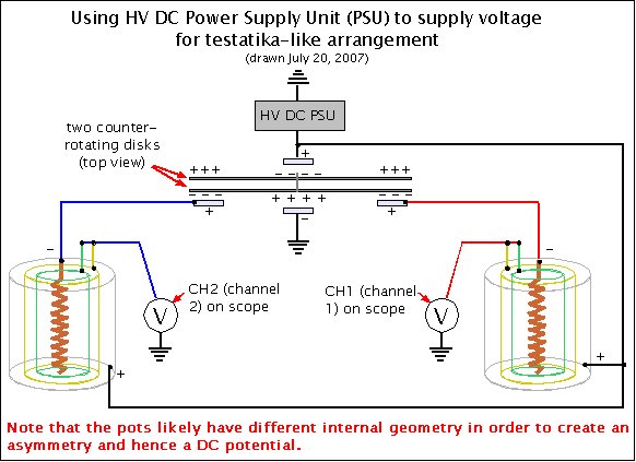
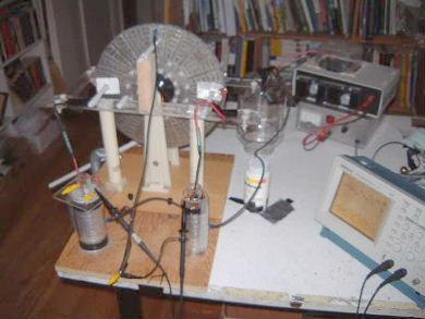
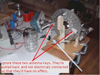
The following is the circuit that was tried using what was built thus far.
Allowing for the difference in how the
HV is supplied, pretty much all of
it can be found in one way or another in the testatikas.
Front view.
 |
|
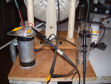
Back view.
 |
|
Pots with different interior geometry were tried. Note that when the PSU was on
there was a large amplitude 20kHZ signal coming from it that made it hard to
see anything else so the PSU would be turned on briefly to charge things up and
then turned off. At that point, due to leakage in the system, the voltage would
drop quickly. It's during this brief period that tests were done.
IMPORTANT! Note the use of two very different pots to
give asymmetry. The exteriors can be alike. It's the interiors that count.
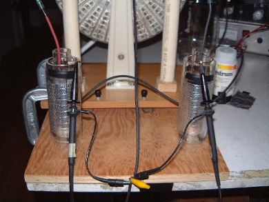
The pot on the left is a mark 2 pot (actually mark 3
which has taller cylinders than a mark 2 for better insulation) and the pot
on the right is a mark 4 pot.
 |
|
The internals of the mark 4 pot used.
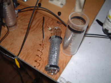 |
|
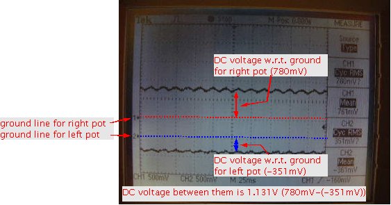
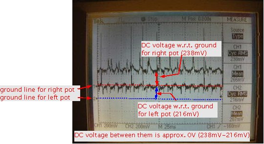
The result of using different internal geometry for pots is
that there is now a DC voltage between their outputs. Here is the output
measured as in the above circuit diagram just after the PSU was turned off and before
the voltage dropped too much. The disks were not rotating. The waveform is the
60Hz household AC.
 |
|
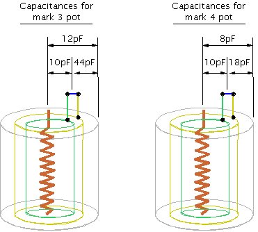
The 18pF capacticance above is much smaller than the 44pF capacitance due to
there being a larger gap between the outer electrode and the outermost of the
middle grid cylinders.
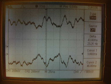
The scope output below shows voltage output while the disks are rotating around
1 or 2 RPM. Note that the two are 180 degrees out of phase. i.e. When one is positive
the other is negative and vice versa. The larger peaks occur due to wobble in the
back disk. When one edge of the back disk is closest to an antenna key the peaks are
at their largest. This happens twice per rotation. Each complete cycle seen below
represents the passage of a sector behind an antenna key.
Output with disks rotating.
 |
|
Current was also measured. No DC current was seen. Small AC current was seen. It started
out at around 5.9uA and dropped more quickly than the voltage dropped. My guess is that
this was the 20kHZ interference from the power supply that disappears quickly after
it is turned off.
To verify that different internal pot geometries were making the DC voltage, two
relatively identical pots were tried, both mark 4s. The result shows that with
two identical pots the DC voltage between them is zero.
The result of using identical (approximately) internal geometry for pots is
that there is no DC voltage between their outputs. Here is the output
measured as in the above circuit diagram just after the PSU was turned off and before
the voltage dropped too much. The disks were not rotating. The waveform is the
60Hz household AC. Ignore the extra noise.
 |
|