Paraffin Wax Dielectric Constant (1st attempt)

Results - No good

This method of construction lead to a less than good measurement. During drying of the wax there was shrinkage that went right down to between the electrodes. This meant having to pour more wax to fill in the gap. This lead to layers between the electrodes and to a breakup of the wax during carving.

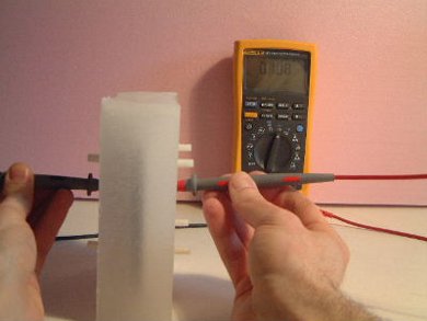
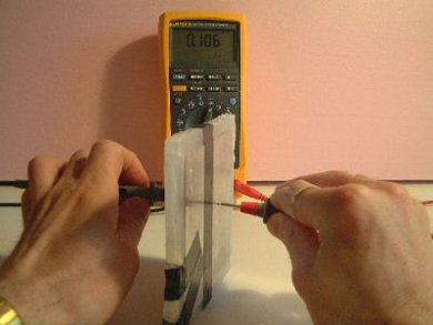
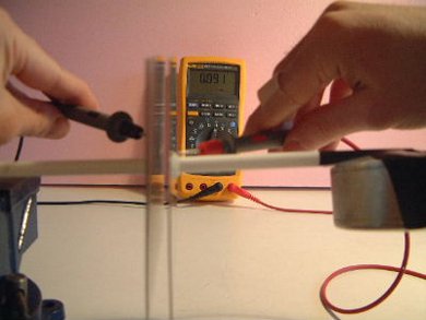
The dielectric constant as determined by the method below is: 1.16. Due to the breakup of the dielectric, this result is useless. 1.16 is the capacitance of the wax capacitor (0.106 nF) divided by the capacitance of the air capacitor (0.091 nF).

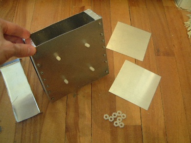
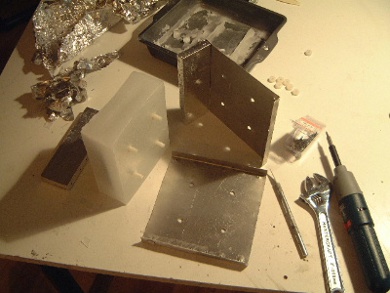
The test was made using a parallel plate capacitor where the plates were aluminum of dimensions .8mm x 101.6mm x 101.6mm. The spacing between the plates was 7mm. To calculate the dielectric constant two capacitors were made: one with paraffin wax for the dielectric, the other with air for the dielectric. The dimensions were the same for the both capacitors. The capacitance of each was measured using the capacitance measuring feature of a Fluke 187 True RMS Multimeter. The three measurements made are detailed in the pictures below.
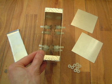
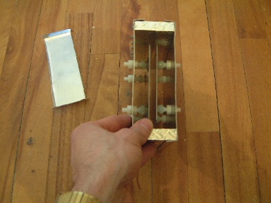
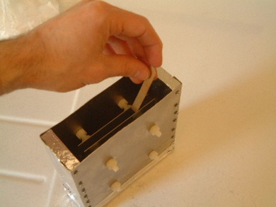
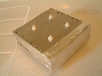
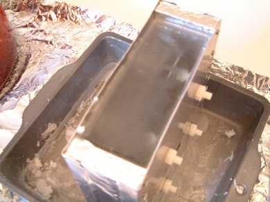
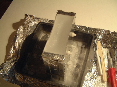
A measurement was made with the capacitor fully encased in wax. The result was 0.108 nF.
The measurement in this case was 0.106 nF. Note the electrical tape on the corner holding the broken pieces in place.
The measurement with air was 0.091 nF.

Construction

The idea was to have fine control over the distance between the electrodes without interfering with the dielectric in between. This was done by holding the plates in position using suction cups where the suction cups were holding from the outer sides of the capacitor's electrodes (plates). See pictures below.

Looking inside at the suction cups that will hold the plates. The plates are on the right sitting on the floor. Each suction cup is made of plastic and is epoxied to the head of a nylon bolt. The part to the left is the base.
A view showing the nylon bolts sticking through the mold wall.
The plates now inside the mold, held in place by the suction cups. The spacing between the plates is 9mm though due to the pressure of the wax the final spacing may be different.
The spacing was measured by cutting a piece of cardboard 9mm wide. Note that the cardboard was actually used while the plates were being attached to the suction cups (i.e. before the picture to the left was taken) but I didn't think to take a picture at the time and now that the base was attached I wasn't about to detach it for a photo.
This shows the base attached using aluminum tape. The aluminum tape is the best I've found for working with liquid wax due to its ability to take the heat. However, it is not ideal. In fact the tape in this picture allowed to wax to leak and I had to retape it much more and even that leaked somewhat!
The area where I poured the wax. The wax was melted on the stove on the left.
The mold heating up in the oven. I wanted it to be hot so that there wouldn't be too much of a difference in temperature between the mold and the wax. This was to get more even cooling around the electrodes.
The complete set of tools for the pouring. Note the digital thermometer on the right. The mold actually leaked at about half height. I had to wait a while for it to cool to about 62 degrees C before pouring in the rest.
The filled mold when it was starting to solidify. Note that due to the shrinkage that happens when solidifying the wax gradually formed a deep depression that went all the way down to about 2mm below the height of the electrodes. I then topped it off with some more hot wax.
The topped off wax. This is taken the next day.
The complete thing after disassembly. The wax block is beautifully smooth with no sign of bubbles, cavities, of cracks within it. My best ever. This was probably due to the preheating of the electrodes and the hot starting point of the wax.
View with a light behind it to show the electrodes within.
Side view of the electrodes in the wax.
Another view of the electrodes in the wax.
rimstar.org
Contact:
Liked this? Share it with: