This was my first successful barium titanate cylindrical capacitor.
Its dielectric constant was 15, which may not sound like much except
that the dielectric constant for most materials accessable to
DIYers/hobbyists is around 2 or 3. It's a mix of 80% barium titanate
and 20% epoxy, the epoxy acting as a binder and as something to have
between the barium titanate molecules in place of air (which has a
dielectric constant of just 1 versus the epoxy's 2.2).
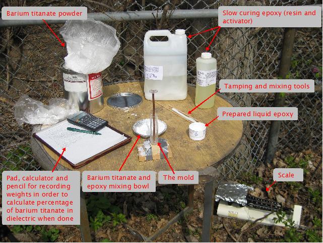
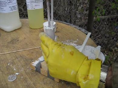
Making the barium titanate and epoxy dielectric
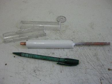
The above was the setup that was used. The mold was two halves of a
transparent arcylic cylinder taped together. Running down the length
of the mold, inside, was the central electrode for the capacitor, a
1/4" diameter copper rod. A spacer was attached to the bottom of the
mold with the rod running up through it.
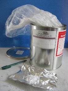
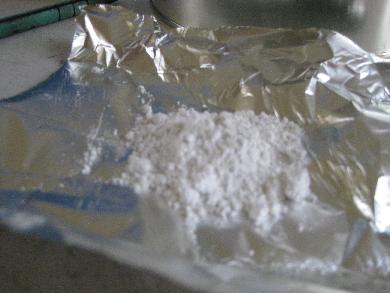
I purchased 12 lbs of barium titanace (product no. BA-901) from Atlantic Equipment
Engineers in about mid 2002. It arrived in a 1 gallon can containing a
plastic bag with the barium titanate in powder form, 99.9%, 0.5-3.0 micron.
I don't recall how much I paid but it was afordable. Their website is
http://micronmetals.com.
The selection of epoxy was not important other than that it was slow
curing to give working time to get it all into the mold. It took about
45 minutes to do so.
The weight of the barium titanate powder and the epoxy used were both
worked out so that the percentage used by weight could be calculated.
Previous attempts had been made with the binder and barium titanate in
liquid form once mixed together but this meant having too low a percentage
of barium titanate to have a relatively high dielectric constant (details
of these failures can be found
here).
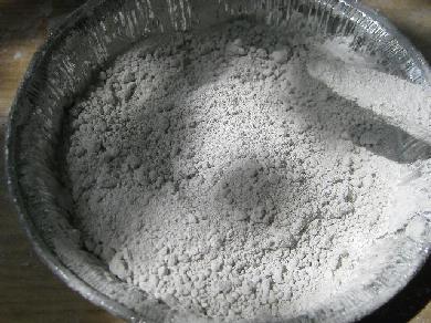
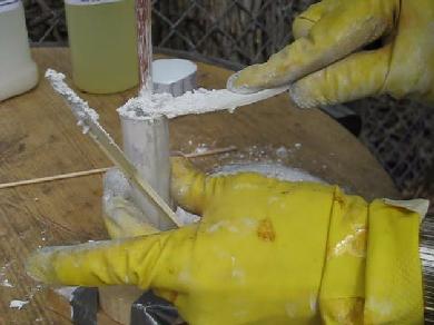
So the method that finally worked was to use a slow curing epoxy
mix that was a sludge that would be pushed into the cylinder a little at
a time and tamped. As the following photos show, this consisted of placing
some of the sludge on the top edge of the cylinder and then tamping it
down with a stick and repeating this until the cylinder was full.
Putting a little of the thick mix on top of the cylinder.
 |
|
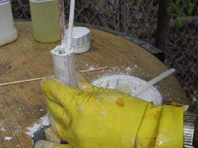
Pushing it down the cylinder and tamping it with a blunt stick.
 |
|
June 12, 2010 - Since working out the process, I've made a few cylinders using the same
mold as in this April 15, 2010 entry. But this time while mixing
the barium titanate and epoxy I kept cutting it into smaller and smaller
pieces, repressing it together, cutting again, and even added more powder
at one point. I ended up with mostly 1mm or smaller diameter balls
with 86% barium titanate. I dropped them into the mold a little at a
time and tamped (pressed) them down firmly before dropping in more.
The result was a K of 27!
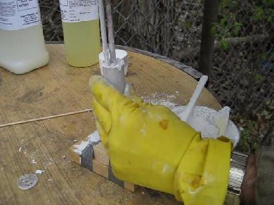
As the cylinder was filled, efforts were made to make sure the
copper rod was centered. As the following photos show, this was
done by placing the end of the tamping stick at the top between the
rod and the inner edge of the mold and observing how much space
remained. The rod was moved as needed.
Checking on the left...
 |
|
... and then on the right.
 |
|
After giving it 24 hours to harden, the mold was cracked open.
The dielectric constant is the ratio of the capacitance of the capacitor
with the dielectric being tested to the capacitance of the same capacitor
but with air as the dielectric.
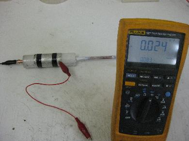
I decided to measure the dielectric constant before removing the
mold, just to see how much difference the acrylic mold would make.
So I first wrapped an aluminium mesh around the whole thing and
measured the capacitance with the dielectric, attaching one of the
meter probes to the copper rod and the other to this mesh
and getting 24pF (see left
photo below.) Then I
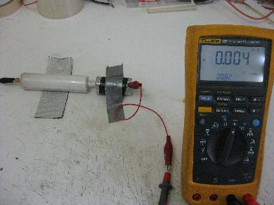
simply slid the mesh off of the dielectric to the long part of the
rod that was not covered in dielectric material and repeated the
measurement, giving the the capacitance of the same capacitor but
with air as the dielectric and getting 4pF (see right photo below.)
24pF divided by 4pF gives a dielectric constant of 6,
not bad.
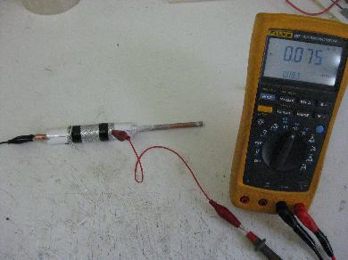
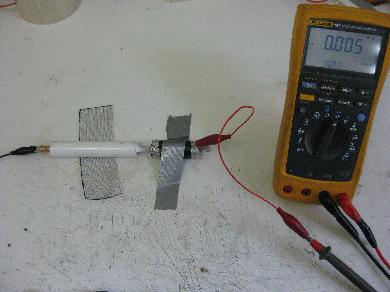
Next I removed the barium titanate and epoxy cylinder from the mold
and redid the measurements as in the photos below.
The results were 75pF with the dielectric and
5pF with air. 75pF divided by 5pF is
15, a very good result or at least good enough
for my purposes.
IMPORTANT: Before measuring capacitance using a
meter like this you must first put the meter probes near the capacitor
electrodes/plates but not touching. Do hold hold them there since your
body will affect the measurements. Record the value you get and subtract
it from the value you get when the probes are in contact with the
electrodes/plates. The problem is that the meter and the probes also
introduce capacitance and you have to take this into account and remove
it from the measurement of your capacitor. After all, you can to measure
the capacitance of the capacitor, not the capacitor plus meter plus probes.
Many meters have a button you can press to have the meter remember this
value and zero out the display for the subsequent measurements. I already
did that step before doing the measurements in the above photos.