Convert ATX PC power supply for USB and other sources
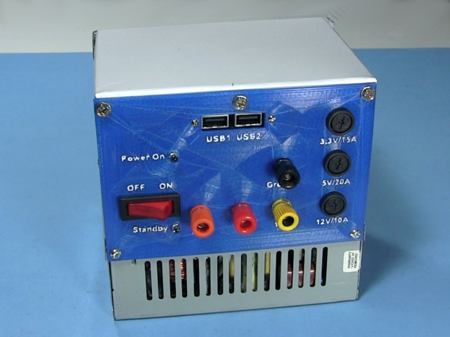
Here's how to convert an ATX PC power supply so that it has USB ports for supplying power over USB cables and also has the usual other voltage available too: +3.3V, +5V, +12V. I didn't bother with the -5V and the -12V but they're easy to add by duplicating some of the steps below.
Most modern desktop computers use some variation of the ATX standard for their power supplies.
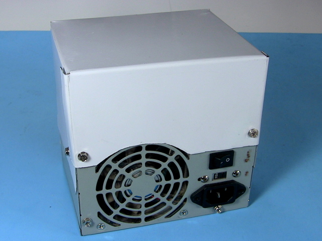
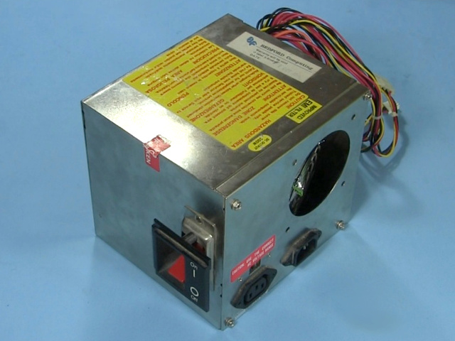
Here are what some power supplies look like when taken from computers. I used the irregularly shaped one since it was rated for 400 watts and the more boxy one was 200 watts.
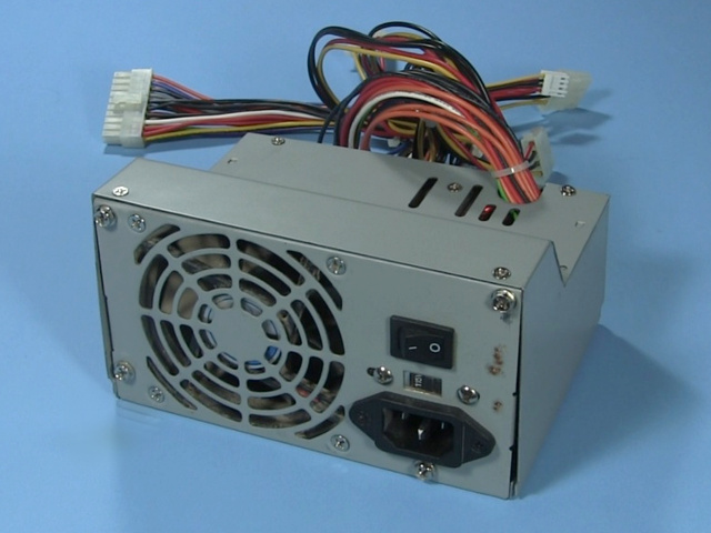
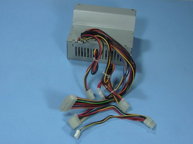
The wires/Molex connector
The connectors on the ends of the wires are called Molex connectors. Which pins of the connector do what is part of the ATX standard. Notice that there are a variety of colors to the wires. Since wires of every color go to the biggest connector, we'll look at that one.
Note that there are 20-pin ATX connectors and 24-pin ATX connectors. Both are shown below.
20-pin ATX Molex connector pinout
Here's the connector with the pins numbered.
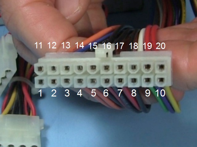
Here's what the pins mean.
| 1 | +3.3V |
| 2 | +3.3V |
| 3 | GND/common |
| 4 | +5V |
| 5 | GND/common |
| 6 | +5V |
| 7 | GND/common |
| 8 | Power all OK, +5V |
| 9 | On standby, +5V |
| 10 | +12V |
| 11 | +3.3V |
| 12 | -12V |
| 13 | GND/common |
| 14 | Power on switch |
| 15 | GND/common |
| 16 | GND/common |
| 17 | GND/common |
| 18 | -5V |
| 19 | +5V |
| 20 | +5V |
24-pin ATX Molex connector pinout
Here's the connector with the pins numbered.
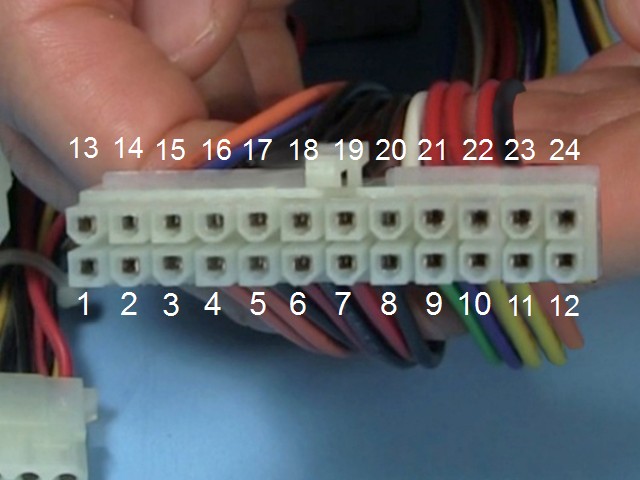
Here's what the pins mean.
| 1 | +3.3V |
| 2 | +3.3V |
| 3 | GND/common |
| 4 | +5V |
| 5 | GND/common |
| 6 | +5V |
| 7 | GND/common |
| 8 | Power all OK, +5V |
| 9 | On standby, +5V |
| 10 | +12V |
| 11 | +12V |
| 12 | +3.3V |
| 13 | +3.3V |
| 14 | -12V |
| 15 | GND/common |
| 16 | Power on switch |
| 17 | GND/common |
| 18 | GND/common |
| 19 | GND/common |
| 20 | -5V |
| 21 | +5V |
| 22 | +5V |
| 23 | +5V |
| 24 | GND/common |
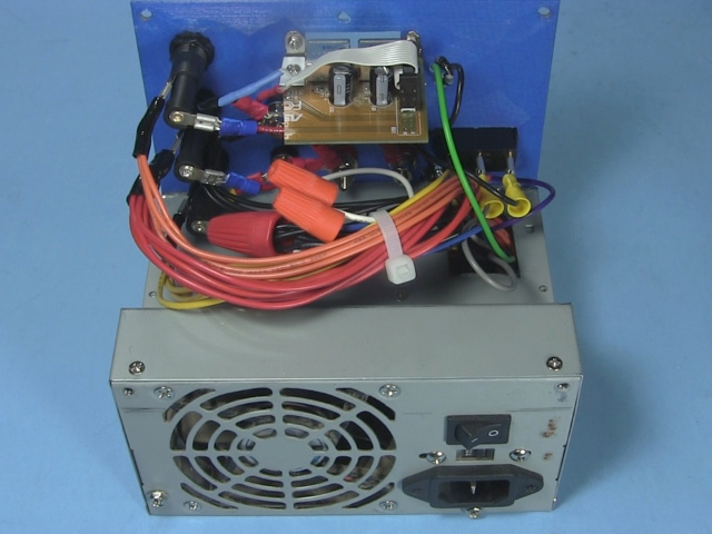
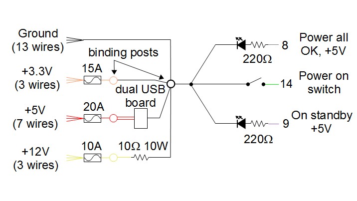
Schematic for converting a ATX power supply
The following it the schematic for how I wired it. Notice that I didn't bother with the -5V and -12V. I also put easy-to-replace fuses for each voltage since the power supply's fuse was soldered in place and buried inside the power supply.
Video - Convert ATX Computer Power Supply for USB
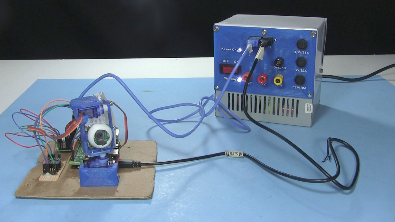
The following video goes through all steps to converting a power supply. It goes from removing it from the computer to making a front panel to wiring it up and testing. It also includes how to add USB ports.
