The objective of this experiment was to test if I could observe that
dissimilar metals have different net charges, and will produce a voltage
when placed close to each other. This could possibly be used in the
testatika to start with a specific polarity. I also wanted to see their
behavior when rotated past one another.
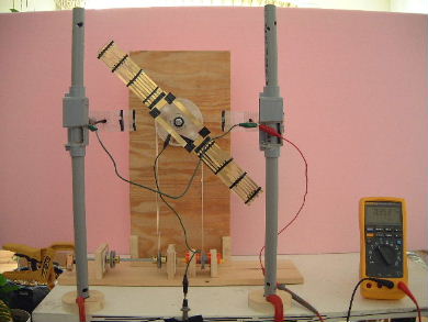
The Setup
In looking at tables for the
galvanic series I chose aluminum for the negative charge electrode
(anode) and brass for the positive charge electrode on the rotor (cathode).
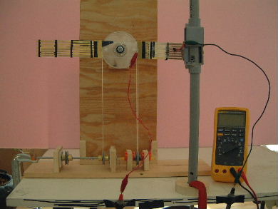
I used this
rotor that I'd built for testing testatika related things.
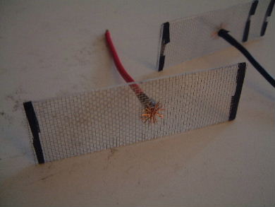
The aluminum mesh with acrylic backing.
 |
|
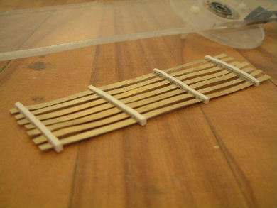
The brass segments. The backing is acrylic but the
brass will not touch it. Instead the brass is held by plastic spacers
which provide better insulation from each other. This will also reduce the
charge interaction with the acrylic.
 |
|
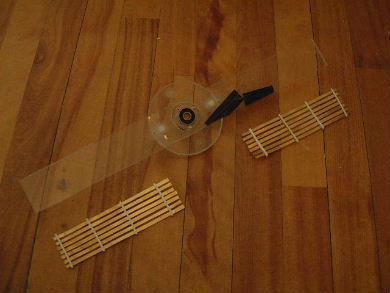
The rotor that the brass segments will be attached to.
 |
|
The Results
I first tried with all the brass segments connected together across the
middle of the rotor. The picture below shows this. The results were too
unstable and nothing could be concluded.
I then switched to testing with only one segment.
Note that all the brass
segments on each side are connected to each other using a brass strip.
That is the strip that the red connector is clipped to. The brass segments
on the left were not involved in these tests.
 |
|
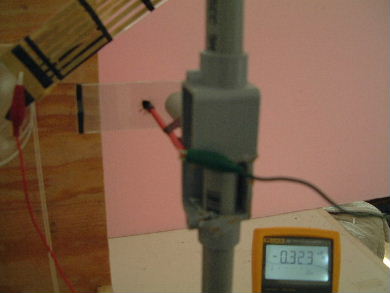
Result immediately after being swung up away from the aluminum.
It then quickly went to 0V.
 |
|
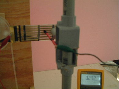
Result after being swung in front of the aluminum. It then
quickly went to 0V if kept there.
 |
|
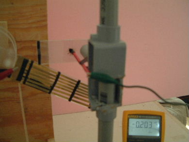
Result immediately after being swung down away from the aluminum.
It then quickly went to 0V.
 |
|
The fact that it went positive when in front of the aluminum makes sense
since aluminum has a negative charge compared to the brass. The aluminum
is connected to the negative probe (black) of the digital multimeter and
the brass is connected to the positive probe (red). The interesting thing
is that the measurement briefly goes negative when swung away. I would
expect it to go to 0V right away without going negative first.
Perhaps that has something to do with the fact that the
end of the brass with
the probe's connector is closest to the aluminum when it is swinging away.
The majority of the brass is now farther away from the aluminum. That
larger amount of brass has the net positive charge and there is very
little positive charge where the probe's connector is. The result is
that the black probe wire is more negative than the red probe wire
is positive.
I also tried without the plastic spacers. That means the brass was in direct
contact with the acrylic. That allowed the brass and aluminum to be closer
together (1mm instead of 3mm apart). The measurement results
behaved the same way but the voltage was less. This is surprising since
they are closer together but possibly the acrylic was taking some of the
charge away.
Note that everything was grounded before testing and my hand that was
on the crank was grounded at all times.