The objective of this experiment was to test if spark gaps could be used
to pulse the intermediate grid cylinders in pots in order to tap into
an energy source, thereby producing excess energy. To do this, a
Wimshurst machine was used as the high voltage source but with the
Wimshurst machine's spark gap and Leyden jars replaced with tetatika style
pots with a spark gap at the top of each. Note that this
geometry for the pots and pulsing them with a spark gap is similar
to the conversion switching tube and used in Edwin V. Gray's device
(see US patents
4,661,747
and also
4,595,975
and
3,890,548)
though EV Gray does not make any claims in his patents for tapping of any
energy source. This similarity between the testatika's pots and EV Gray's
conversion switching tube has been pointed out many times over the years.
The configuration that seems to work
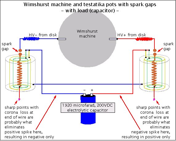
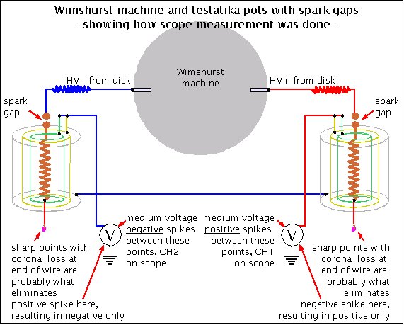
The following diagram shows what gave the desired result, namely DC output at
the pots.
The whole trick in getting DC was to have the corona leakage using the sharp
points at the bottom of the coil electrode that is in the middle of the pots.
The above diagram shows this leakage. Without this leakage, the output consisted
of alternating spikes, AC.
|
|
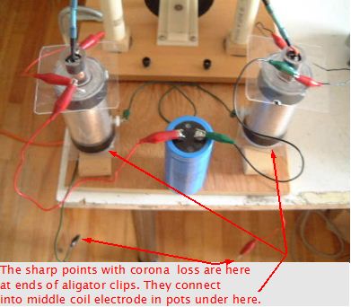
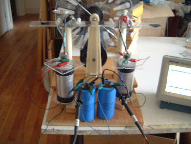
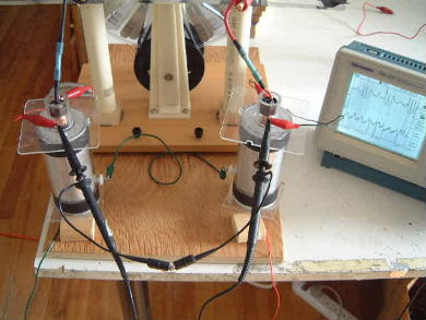
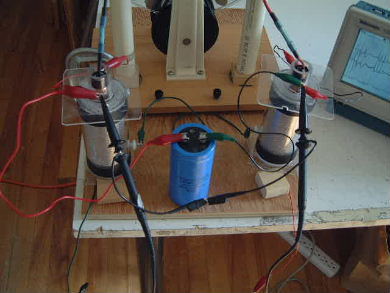
The complete setup with the capacitor as load.
 |
|
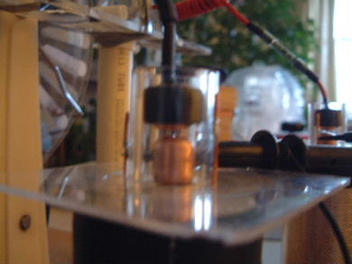
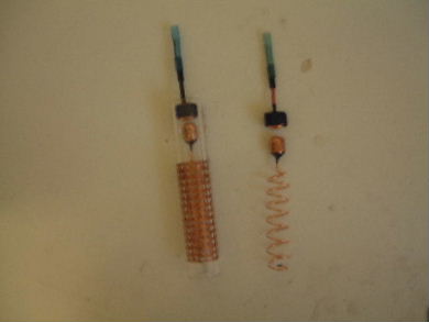
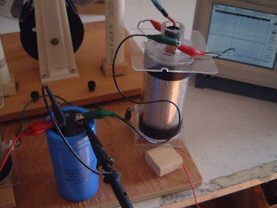
The spark gap and center coil electrode. On the left is showing
the components in place in the centermost acrylic cylinder.
 |
|
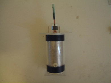
A completed pot. These pots are just slightly enhanced
versions of the mark 2 pots.
 |
|
|
|
|
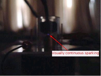
If the discs were spun up to around 380-400RPM then some of the spikes started to
join at the top forming a more pure DC voltage output and even the bottom of the
spikes moved away from the zero line producing all DC voltage as the photos below
show.
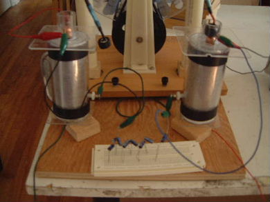
Making the measurement that gave the output below.
 |
|
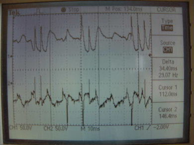
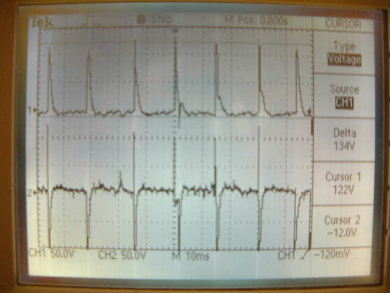
The oscilloscope output with the discs at around 380RPM.
The top trace is the right pot, and the bottom trace is the left pot. Notice
the top trace is all positive and the bottom trace is all negative. Both are
DC.
 |
|
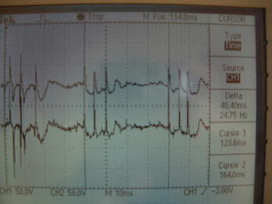
The oscilloscope output with the discs rotating at a slower
speed. The spikes are not merged at this speed.
 |
|
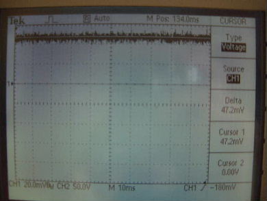
I next put the capacitor in place and ran the test again while measuring on the
oscilloscope. See the following photos. Note that the scope does not show the
nice DC and yet the
capacitor was charged from 0V (zeroed and checked before the test) to 47mV
over a period of about 10 seconds with a disc speed of around 380RPM.
The capacitor was a 1940microfarad, 200VDC electrolytic capacitor. Using the
formula for power in a capacitor, (1/2)CV^2, that means the power in the
capacitor as a result of the test was 2uW (2 microwatts). Clearly no energy
source was being tapped here, or at least not in any measurable amount.
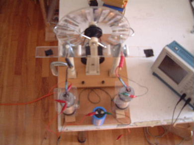
Charging the capacitor while measuring the output
of the pots.
 |
|
The scope output. Not much DC and yet the capacitor
was charged so the presence of the capacitor must be affecting the
measurement.
 |
|
Measuring the voltage on the capacitor.
 |
|
The 47mV on the oscilloscope.
 |
|
Other capacitor tests
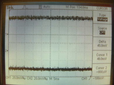
At the suggestion of someone through private email, I
added a second 1940uF capacitor in series with the first and ran
the system with the intermediate terminals of the capacitors grounded.
|
|
CH1 is the capacitor on the right, CH2 the capacitor
on the left. Note that CH2 is negative because the oscilloscope's probes are
the reverse of the way they are for CH1.
 |
|
Based on the results, see results for 2nd test below, I decided to do another test with a lower
capacitance by stringing a bunch of smaller capacitors in series. The reason
for using multiple capacitors is that they had a breakdown voltage of only
25V and I wanted to be able to withstand up to 200V.
Here are the results fo all three of the above capacitor combinations
and some interesting calculations.
1st test: one 1940uF, 200V electrolytic capacitor
discs were rotated by hand crank 425 +/- 10 RPM for 10 seconds
- voltage on capacitor after run = 39mV
Measured total voltage = 39mV
Measured total capacitance = 1940uF
Calculated total energy in capacitor = 1.475uJ, E=1/2C(V^2)
Charge stored in capacitors = 75.7uC, Q=CV
2nd test: two 1940uF, 200V electrlytic capacitors in series
discs were rotated by hand crank 425 +/- 10 RPM for 10 seconds
- voltage on right capacitor after run (CH1 on scope picture above) = 40mV
- voltage on left capacitor after run (CH2 on scope picture above) = 42mV
Measured total voltage = 82mV
Measured total capacitance: 1/Ct = 1/C1 + 1/C2, Ct = 970uF
Calculated total energy in capacitors = 1/2(C)(V^2) = 3.26uJ, E=1/2C(V^2)
Charge stored in capacitors = 79.5uC, Q=CV
3rd test: 8 22uF,25V electrolytic capacitors in series
discs were rotated by hand crank 425 +/1 10 RPM for 10 seconds
- voltage across all capacitors after run = 15.8V
Measured total voltage = 15.8V
Measured total capacitance: 1/Ct = 1/C1 + ... + 1/C8, Ct = 2.75uF
Calculated total energy in capacitors = 343uJ, E=1/2C(V^2)
Charge stored in capacitors = 43.5uC, Q=CV
Notes: The 3rd test was done 2 days after the other two. Also, even though
the capacitances for the 2nd and 3rd tests above are calculated, the
individual capacitances were checked by measurement.
The reason for the higher energy capture is simply because of the
decreased capacitances. This is expected since by decreasing the capacitance
you will generate more voltage within the capacitor for every charge you
put on the capacitor plates (the resulting V in C=Q/V is larger for smaller
capacitances.)
Another way of thinking of it is that for every charge put on the plates of
the capacitor, a stronger electric field will be generated between those
charges. Being able to generate more voltage is like having a spring that
you can stretch more, all other things being equal. You're storing more
energy in the spring for when you release it, just as you're
storing more energy in the capacitor for when you discharge it.
So we're just changing the capacitors so we can store more of the available
energy. Nothing here indicating that we are generating more energy.
Conclusion
The small amount of charging of the capacitor above demonstrates that there is definately no
energy source being tapped here.